I am having troubles connecting an Omron Photomicrosensor (https://www.omron.com/ecb/products/pdf/en-ee_sx3160_w11_4160_w11.pdf) to my arduino UNO. Right now I have the Output in an Analog Pin, the Power supply lead in the 5V pin and the Ground lead in the GND Pin. There are two other leads, the anode and cathode that I am unsure what to do with, I connected them to an external power supply.
I am using the photomicrosensor to help move a stepper motor that i already have working on my board. I am using a Leadshine Driver to do this.
I am new to the Arduino world, just started yesterday, so I don't know much.
I am still having issues with the photomicrosensor. I will attach a schematic of how i am connecting it all.
The problem is when I print the AnalogRead of the A0 pin (the pin connected to the output of the photo sensor) the numbers are all whacky. When the LED is transmitted, the value remains 0. When I interupt the transmission with paper/finger, the values range from 0-1023. I didn't think the values would be able to get above 1000. For example, when the transmission is blocked, the readings go 1023 0 780 1023 670 0 890 890 670 1023 etc etc. This is when it is continuously looping without a delay.
When I add a delay, 1 second for example. The reading will decrease and then increase, starting with 1023. It will go from 1023 down to 0 then back up to 1023. When nothing is blocking the LED it is always 0.
Thank you for the reply. I used a 10K resistor initially and the values remained at 0 regardless if the LED was being transmitted or not. What do you mean by "floating". Sorry I am new to this.
"floating" is an open, unconnected input, which can happen if the sensor is not properly connected to the Arduino GND. The values that you read will vary randomly due to static charges, such as you described.
Please post a corrected schematic, showing ALL connections to the sensor and the Arduino.
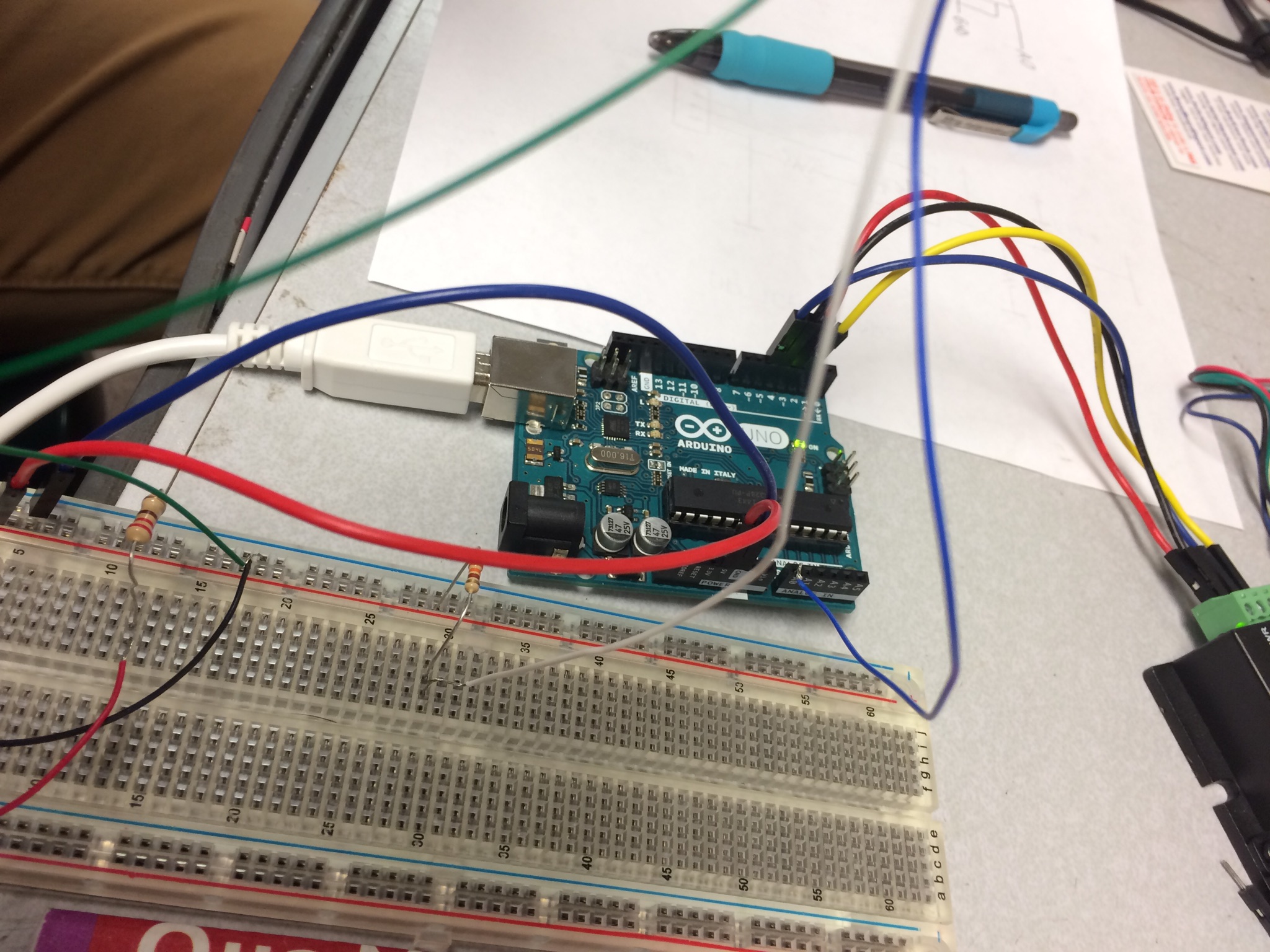
I am unsure how to draw the schematic correctly if my previous one was incorrect. I will send you a picture. The thin blue wire is the output which is connected to A0, it runs directly from the photomicrosensor. The 5v pin on the arduino travels to the breadboard.The white wire is the Vcc which has a 330 ohm resister preceding it and is connected to the portion of the breadboard with the 5V pin. The thin red lead is the anode and has a 220 ohm resister preceding it, also connected to the 5v pin. The green wire is ground which is connected to the GRND pin of the arduino. The black wire is the cathode which is also connected to the GRND pin.
I will attach the picture. I really appreciate all the help. I know I am probably not explaining it the best way but i am inexperienced and dont know how to draw a "correct" schematic. Maybe you could help me wiht this.
The photo is useless, because it does not show the sensor.
On a schematic, a line indicates a wired connection. Can you really not see that on the schematic you posted, A0 is connected to GND?
Edit: I now see the problem. There are 5 pins on the sensor and the output is open collector. You need three connections to 5V, two with resistors to the "O" and "A" pins, and two connections to GND as shown in the schematic below.
The inverted triangle is the schematic symbol for GND.
These sensors are sensitive to environmental light, and need to be shielded from that.
A white piece of paper is probably not blocking all the IR light.
Leo..