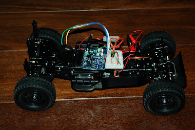
I was wondering how to connect this ESC to my Arduino board. If I connect my 7.2V battery pack to the ESC, the
servo-like connector of the ESC will deliver 5V which could power the Arduino.
The question is how to connect the control pin (orange wire of the servo-like connector).
Should I control this ESC like a servo, so firing pulses at 50 Hz and modifying the width of the pulses to control the voltage that goes
to the motors, or should I use one of the Arduino PWM pins in high frequency to control the ESC.
It would also be great if someone could point me to a datasheet of a ESC like this.
Do you have all the pieces? What do you want the arduino to do?
The connection from the receiver to the main part is the only point I can see where the arduino could be connected. If you have the transmitter you can figure out what those pins from the receiver do and what voltages are on them.
Do you have all the pieces? What do you want the arduino to do?
What I want the Arduino to do is control the ESC. So the arduino should control the direction and the speed of the motor that is connected to the ESC. Since the the motor can draw up to 50 A I can't connect the motor directly to the Arduino, so using this ESC would be a nice option.
Yes, you control this sort of speed controller like you would a servo, with a 1-2ms pulse 50 times a second or so. You can probably use one of the existing 'servo' libraries, even...
You didn't say if you had the transmitter, the receiver, a pinout or the voltages on those pins.
The cable/connection you need to concentrate on is the one going to the receiver.
I do have the transmitter and the receiver. The connection between the receiver and the ESC is the three pin servo connector.
Two pins (red and brown) supply 5V to the receiver. The third pin (orange) is probably for controlling the ESC.
This pin delivers 0.16V when the transmitter is in the full backward position.
This pin delivers 0.29V when the transmitter is in the full forward position.
Yes, you control this sort of speed controller like you would a servo, with a 1-2ms pulse 50 times a second or so. You can probably use one of the existing 'servo' libraries, even...
That's what I tried (without success yet). B.t.w. I guess you mean 20ms pulses instead of 2ms?
You power the esc with your 7.2V battery. I don't think you need to use + and - on the connector esc that normally goes to your receiver (Arduino is used as receiver output now). Just wire the orange (signal) wire to the Arduino.
Someone else suggested to use the servo library. I think that should work. I never tried it myself though. Maybe someone else jumps in...
Thanks. That makes sense. I tried this, but it does not seem to work yet.
I sent the same signals as I would sent to a servo via the signal wire. I sent pulses each 20ms.
I would expect that by sending pulses with a width of 500ms I would get maximum revert and by sending pulses with a width of 2000ms I would get maximum forward. Similar to the -90 and +90 degrees of a servo...
Did you mean 500/2000 micro-seconds? Or did you do 500/2000 milliseconds?! You want the former; every 20 millisecond you send a pulse, the pulse would usually be between 1 millisecond and 2 milliseconds long (1000 and 2000 microseconds.) 1.5 milliseconds is usually "center", and there's some variation about how far from center the limits are.
I found This manual that seems to indicate that you might need a special startup procedure to "program" the speed controller. Do you have a regular remote control setup (transmitter/receiver in addition to the ESC) that you can test the setup without any arduino being involved?
Thanks for the startup sequence tip! This makes a big difference.
Great! I was reading about the startup sequence, thinking "that makes sense from a radio-control point of view, safety-wise. You don't connect your motor and have it start running without some explicit interaction with the user. But it's likely to be a real pain to automate!" (I guess not too bad, since you have it working already!)
Can I see the servo codes you used to drive your ESC? Since I also want to control my motor using a K243 motor driver... it says I need to send 1-2ms of pulse.