Hello everyone,
I would like to create an isolated arduino nano without having to power the arduino nano using cable connected to power source.
I have a battery, SPST rocker switch and arduino nano board.
From my understanding, 1 pin of the rocker switch is connected to the ground of arduino nano. The middle pin of the rocker switch is connected to the negative terminal of the battery snap. The positive terminal of the battery snap is then connected to the vin of arduino nano.
Could someone advise whether this is the correct connection?
In addition, does anybody know what code I will have to use for this setup?
Thank you!
Hello
Post a schematic to see how we can help.
Publish the PDF to read it.
It is not.
It will result in the Arduino being powered backwards. Which will almost certainly fry the Arduino.
May I know which part of the connection do I have to change?
You have to change things so that the positive of the battery goes to Vcc through the switch, and the negative of the battery goes to ground.
Exactly what do you mean by that?
If a processor is unpowered you can not connect it to an output that is still powered up, otherwise you get parasitic powering of the unpowered Arduino through the protection diodes. You need to have external inputs go through an opto isolator in order to do this.
Oh I see, so that would mean
Battery (+) connected to middle pin of switch
Middle pin of switch connected to vcc of arduino nano
Battery (-) and side pin of switch are both connected to ground
Is the above correct?
Bt isolated arduino nano I mean I would like to power it using the battery, and control it using the switch. I do not have to connect the arduino nano to a electrical source using the usb cable
Connect the battery - directly to the ground. If you want to switch the ground as well then you would need a double pole switch, but there is no point.
OK but that is not what isolation means in electronics. Will you be connecting this nano to anything that has an output which is active when the nano "could" be switched off?
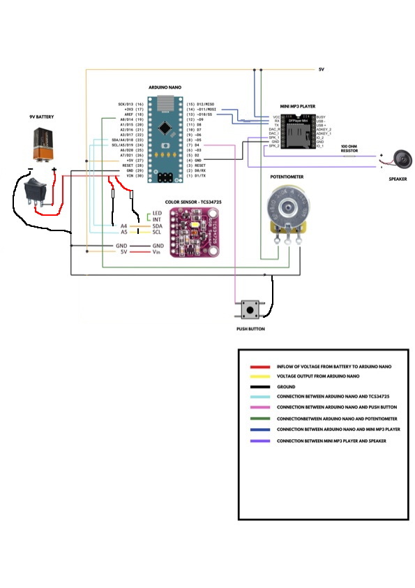
Why have you got a 10K resistor going to the MINI MP3 player? Also you seem to be powering it from 5V, is that what your sort of MP3 plater wants, they normall want 3V3.
Also your switch at the bottom looks wrong, for clarity you should only show two wires going to a switch like this between opposite corners. The switch should be wired between input and ground with no resistor at all. When setting the pin mode for this switch select INPUT_PULLUP for the mode.
The colour sensor looks like it is being talked to with I2C, but you have shown no pull up resistors on the two lines, 4K7 is the normal value to use.
Like this
Please don't include PDF diagrams, because they end up being very small, like this when you edit them.