There are other Topics similar to this on the forum but none of them seem to deal with my problem.
I am a beginner at programming Arduino and usually I am able to find Sketches that will do what I want, with very few changes, on the Internet.
The current situation involves the following article from “Instructibles”.
“How to Control 3 Servo Motors Using Push Button Switches and an Arduino Uno
by Break It Fix It, Published Nov. 1, 2015.”
The Sketch and wiring work exactly as described and I am pleased with that. I have attached the original sketch from Instructible at the end.
My problem comes from the MG90G Micro Servos I am using, they do not all respond the same to the movement commands.
I need to be able to fine tune the Min and Max movement for each servo independently. I can adjust all three servos by varying lines 11 and 12 without a problem and they all seem to respond to changes similarly, but the same.
I then tried to control each servo independently by using lines 31 to 38 which does not seem to accomplish what I want.
I have tried quite a few variations and am getting more confused and frustrated, obviously using a working Sketch from a reliable source by a rank amateur is not the best way to do things but that is where I am at.
Does someone knowledgeable see a way to accomplish what I wish to do in a way that I will be able to work with?
Thank you, I hope this clear and in the correct format to make it easy..
Always include your sketch using the <CODE/> formatting tool.
#include  <Servo.h>

Servo myservo;  // create servo object to control a servo1
Servo myservo2;  // create servo object to control a servo2
Servo myservo3;  // create servo object to control a servo3

int pos = 90;    // variable to store the servo's starting position as Down.
int pos2 = 90;
int pos3 = 90;

const int maxDeg = 110; // limits the maximum range of the servo's movement to 110 Down
const int minDeg = 70;   // limits the minimum range of the servo's movement to 70 Up

const int movement = 2; // distance to move servo (eg. 2 is small 20 is large movement)

// This basically means the servo will sweep from 90 to 105 (not 0 to 180 as expected), you can adjust this to suit your own servo motors specs

const int leftPin = 2; // tells the Arduino the location of  the signal cable from the switch
const int rightPin = 3;

const int leftPin2 = 4;
const int rightPin2 = 5;

const int leftPin3 = 6;
const int rightPin3 = 7;

const int outputPin = 8; // tells the Arduino the location of the signal cable to the servo
const int outputPin2 = 9;
const int outputPin3 = 10;

int leftPressed = 0; // variables we will use to keep information about the switch states
int rightPressed = 0;

int leftPressed2 = 0;
int rightPressed2 = 0;

int leftPressed3 = 0;
int rightPressed3 = 0;


void setup()
{
myservo.attach(outputPin);  // attaches the servo motor's signal cable location, stored in the variable outputPin, to the servo object
myservo2.attach(outputPin2);
myservo3.attach(outputPin3);

pinMode(leftPin, INPUT); // sets the state of the pins to input mode
pinMode(rightPin, INPUT);

pinMode(leftPin2, INPUT);
pinMode(rightPin2, INPUT);

pinMode(leftPin3, INPUT);
pinMode(rightPin3, INPUT);
}

void loop()
{
leftPressed = digitalRead(leftPin); //gives a value to the variables as the state of the switch
rightPressed = digitalRead(rightPin);

leftPressed2 = digitalRead(leftPin2);
rightPressed2 = digitalRead(rightPin2);

leftPressed3 = digitalRead(leftPin3);
rightPressed3 = digitalRead(rightPin3);

// The following routine handles what happens if the first set of push buttons are pressed

 if(leftPressed){
   if(pos < maxDeg)
     pos += movement;
     myservo.write(pos);             // tells the servo to go to the position stored in the variable ‘pos’
      }

 if(rightPressed){
   if(pos > minDeg)
      pos -= movement;
      myservo.write(pos);             // tells the servo to go to the position stored in the variable ‘pos’
     }

// The following routine handles what happens if the second pair of push buttons are pressed

 if(leftPressed2){
   if(pos2 < maxDeg)
      pos2 += movement;
      myservo2.write(pos2);
   }

 if(rightPressed2){
   if(pos2 > minDeg)
      pos2 -= movement;
      myservo2.write(pos2);
      }

// The following routine handles what happens if the third pair of push buttons are pressed

 if(leftPressed3){
   if(pos3 < maxDeg)
      pos3 += movement;
      myservo3.write(pos3);
      }

 if(rightPressed3){
   if(pos3 > minDeg)
      pos3 -= movement;
      myservo3.write(pos3);
      }

}

 //if(rightPressed3){
 //  ctrl_servo(myservo3, pos3, -1);

 //void ctrl_servo(servo, poss, dir){
 //  if(poss > minDeg)
 //     poss += movement*dir;
 //     servo.write(poss);
 //     }
 //  else;
 //    delay(15);
 //  }
One solution: define an array for the min/max positions of each servo.
const int maxDeg[] = {  // limits the maximum range of each servo's movement
   110, 100, 120
};
const int minDeg[] = {  // limits the minimum range of each servo's movement
   110, 100, 120
};
Then in your code, use the appropriate end points for each servo, e.g.:
   // The following routine handles what happens if the second pair of push buttons are pressed

   if( leftPressed2 ) {
      if( pos2 < maxDeg[1] )
         pos2 += movement;
      myservo2.write(pos2);
   }

   if( rightPressed2 ) {
      if( pos2 > minDeg[1] )
         pos2 -= movement;
      myservo2.write(pos2);
   }
I would get a copy of the Arduino Cookbook and skim it cover to cover and pause on the sections you see interesting. It has schematics, code and an explanation of many projects. If you understand what you are reading you will have the basic knowledge for Arduino.
I don't see the code. Post all of it. In the IDE Edit menu. BTW, there are no line numbers, so either do a screen grab or copy the specific section of code and use the CODE tage in your reply.
Well, you could keep cloning and modifying variables and their names until you achieve the desired behavior. If that would suffice, I'll let others help you through that process.
However, the clone-and-modify-until-it-maybe-works isn't really what you want to do here.
See below for one possible approach. The biggest challenge will be for you to figure out how it works, and what to modify, but the tools are there; even without understanding the code, the data array used pretty much gives it away. Give it a try, get back to us if it's not doing what you want. I'm not around here much anymore, but I'll try to check in tomorrow, see how it's going.
A Wokwi implementation, using negative button logic and INPUT_PULLUP:
and, the code from it, but with your positive button logic:
#include  <Servo.h>
//code written to demonstrate managing N servos with left and right pushbuttons, and varying endpoints.
//limitations - as presently arranged, min position must always be left, and must always be less than max position, else all will collapse in a heap.

struct mystruct {  //defines a structure for all data relating to one servo
  int minpos;  //min value for servo
  int curpos;  //where the servo presently sits
  int maxpos;  //max value for servo
  int leftp;   //left button pin
  int rightp;  //right button pin
  int servop;  //pin for servo
  Servo myservo; //reserves space for the data needed to manage a servo
}; //end mystruct

mystruct servos[] = {//creates 3 instances of that structure in an array
  {70, 90, 110, 2, 3, 8},
  {70, 90, 110, 4, 5, 9},
  {70, 90, 110, 6, 7, 10},  //N.B. compiler generates a warning about an uninitialized component; ignore this
};
const int servoNum = sizeof(servos) / sizeof(servos[0]);   //create constant indicating number of servos managed
const int movement = 2; // distance(degrees) to move servo (eg. 2 is small 20 is large movement per update)

//instead of using delay(ms), we will use the accepted millis() construct for implementing timed events
long unsigned int lastupdatetime = 0;     //tracking variable for the last time we updated the servos
const long unsigned int cycletime = 100;  //we will check the buttons and update the servos every n milliseconds; you can change this to increase/decrease movement speed

void setup() {
  Serial.begin(115200);  //sets up serial for Serial Monitor use, reporting
  for (int index = 0; index < servoNum; index++) {     //manage all setup for each servo sequentially
    servos[index].myservo.write(servos[index].curpos); //write position (presets servo appropriately)
    servos[index].myservo.attach(servos[index].servop);//attach         (begins updates for servo)
    pinMode(servos[index].leftp, INPUT);
    pinMode(servos[index].rightp, INPUT);
  } //end setup loop
} //end setup

void loop() {
  unsigned long int currenttime = millis();           //get time
  if (currenttime - cycletime > lastupdatetime) {     //check to see if it's time to check buttons and update servos; see defn of cycletime and currtime, above
    lastupdatetime = currenttime;                     //update our time tracking
    for (int index = 0; index < servoNum; index++) {  //check, update all servos sequentially
      if (digitalRead(servos[index].leftp)) {         //if left pressed
        servos[index].curpos = servos[index].curpos - movement; //calc new position
        if (servos[index].curpos < servos[index].minpos) servos[index].curpos = servos[index].minpos; //limit if needed
        servos[index].myservo.write(servos[index].curpos);    //write position
      }  //end if
      else if (digitalRead(servos[index].rightp)) { //else if right pressed  (cannot press both, now, can we?)
        servos[index].curpos = servos[index].curpos + movement; //calc new position
        if (servos[index].curpos > servos[index].maxpos) servos[index].curpos = servos[index].maxpos; //limit if needed
        servos[index].myservo.write(servos[index].curpos);    //write position
      }  //end else if
    }  //end servo update loop
  }  //end timed update action
}  //end loop
Note that, to add more servos, you need to add one data line per servo to the array. That's it. Nothing more; the rest self-adjusts. Comments are verbose, to try and clarify.
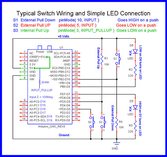
On button wiring; note the following diagram; the two code versions above use arrangements S3(Wokwi, negative logic), and S1(your positive logic).
Not sure of the origin for the diagram, but @LarryD often uses it for assisting newbies, so I'll give him the attribution; he can correct me, if required.
Hope that helps, a little. Question - is this for a model railroad application, perchance?
(edit) - added serial output to the Wokwi version, in case you want to record the final values you arrive at for each servo. You can transfer those lines to the code above, if you wish them.
let’s say we have circuit S1.
Let’s say the switch is 10 feet from the Arduino.
This means we are taking the +5v supply line out 10 feet and 10 feet back.
5v is now extended 20 feet with the potential of it coming in contact with things that can go pop if there was ever a short circuit on the cable.
Also, sending 5v out on a 20 foot wire allows inductive coupling to noise sources that can cause serious problems back at the Arduino.
If we are using S2, the R1 pull-up is back at the Arduino, the switch is 10 feet away as before.
If there was a short on the 10 feet of wire, the external pull-up (R1) limits the short circuit current.
Here's another approach based on the proposal of @camsysca, but with the MobaTools library instead of the simple servo.h. MoToServo can control the speed on its own - so no need to do that in the sketch.
@LarryD I have seen your diagram many times. I have wondered about the claim of external pull down being BAD. This was the first time I have seen an explanation of why it’s bad. Is the greater chance of short circuit with long leads the only reason it’s bad, or are there other reasons?
As far as external switches are concerned, yes that is a major reason.
There are times when I use the S1 configuration for switches.
This is when the switch is mounded in a case containing all the other project components.
You need to keep your wits about you when you use the S1 configuration.
Six months after you make the project, you might not remember the switch is wired to +5V.
While probing around with a screwdriver, scope GND Lead or voltmeter you just might short the 5v connection to another wire or component.
I don't want to hikack someone's thread here, but i have always wondered…Does pull up or pull down use more or less energy, or is it negligible? I have wondered because I make a lot of battery operated projects and use buttons as toggles a lot. So they spend a lot (most) of time released. I have been curious about the different current draws in their “idle” state.
I have read all your responses and tried very hard to make MobaTools version work. At this point I have returned to original sketch that worked but could not provide individual servo control, it causes model train cars to derail but I can live with that until I figure Arduino out.
I have ordered the Arduino CookBook and will work my way through that before attempting more changes.
I m really appreciative of your patience with me and will try to remember to let you know if I get this working the way I want.
@NAP1947 So, did you look at and not comprehend the Wokwi demonstration? Ask questions. You were given a working solution, so the failure to get it working means you misunderstood something pretty basic. Again, ask questions.
Also, I suggest you check your private messages on this forum.
Can you please post a copy of your circuit, a picture of a hand drawn circuit in jpg, png?
Hand drawn and photographed is perfectly acceptable.
Please include ALL hardware, power supplies, component names and pin labels.
Can you post some images of your project?
So we can see your component layout.
What did you try? Does the Wokwi example meet your requirements? Did you try the Wokwi example on your hardware? We cannot help if you don't tell us exactly what you did and what did not work as expected.