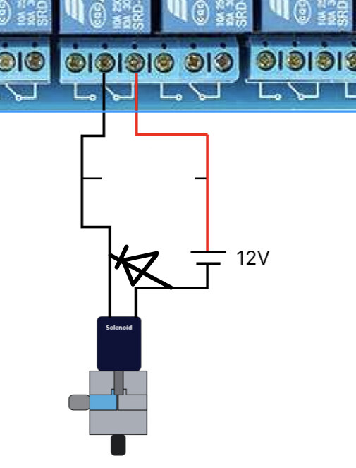
I want to create a digital water curtain. Currently, I am using an Arduino Mega (D0-D53, A0-A13) to control 68 relays. Each relay is connected to one solenoid valve, making a total of 68 solenoid valves. The relay model is 5V low-level trigger. The working voltage of each solenoid valve is 12V,0.13A.
circuit diagram: I am powering the Arduino via USB, providing power to the solenoid valves with a bench power supply (30V/10A), and using an external power supply of 5V/10A for 7 multi-channel relays.
Current issue: When I control all relays separately with the Arduino Mega (without connecting the solenoid valves), there is no problem. However, when I try to power the solenoid valves in the circuit, it often causes the Arduino to reset while it is working. I have observed the current from the bench power supply, and it does not exceed its calculated maximum current. Currently, I am not sure if this is the problem that I need to add a transistor to each Digital pin of the Arduino Mega to prevent kick-back of the current.
The flyback diodes go across the solenoid with the cathode connected to the positive side.
Cleaning up that ratsnest of wires would also help. Keep the wires from the relays to the solenoids away from all other wires
Can I ask what type of flyback diode would be suitable for a solenoid which is drawing 0.13A on a 12V supply? I am not sure about the specification because the relays switch every second to turn off and turn on the valves.
Yes, the flyback diodes will, ideally, be connected directly to the solenoid terminals, or as close to them as possible. If the flyback diodes are a long distance from the solenoid, the wires can act as antennae, sending out radio interference or inducing interference in other wiring.
The flyback diodes are important, but I'm still not sure if that is what is causing the problem here. The 30V supply for the solenoids appears to be completely isolated from the 5V supply for the Arduino and relays. I don't see a common ground.
Can you post a link to the exact relay boards you are using?
How do you have the relay boards wired to the Arduino? If the board has a jumper labeled "JD-VCC" then typically there would be no ground connection between the Arduino and the relay board, only +5V and the signal lines.

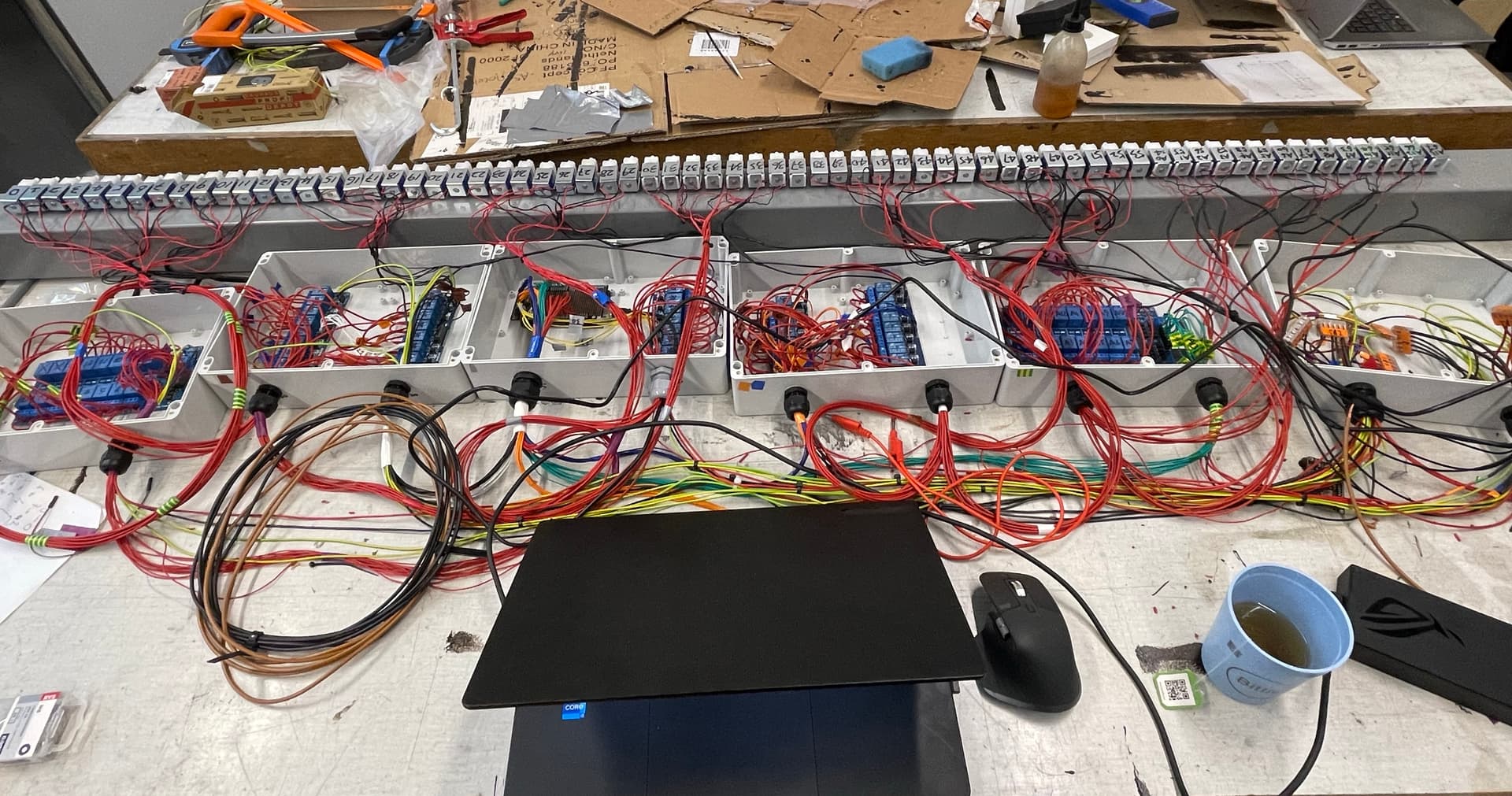
 Is that what you mean in the picture?