Background: In the attached fritzing sheet you see a simple switch wiring as used in the official Arduino examples as well. As soon as I send a digital write from PIN 4 the transistor enters the "open" state so that GROUND and the PIN in the adapter get "connected".
I have the following problem: I need to control the voltage between the GROUND and normal PIN of the SUB-D9 adapter. The normal pin connects to a 10K input and 24V is used in the machine connected to. As I said, the goal is to simply connect the ground pin to the normal pin which triggers a signal in the connected machine. BUT: What's the best-practice to control the voltage between those pins proportionally? How would you e.g. connect a (digital?) potentiometer or are there better solutions? PWM lead to too much "jittering"...
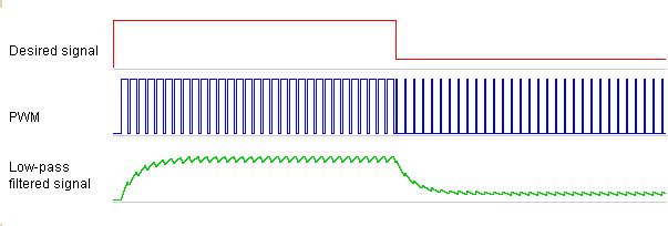
It all depends on what sort of filter you put on the back end of it. The filter you need depends on how much ripple you can tolerate ( do not say no ripple as that is just silly everything has ripple ( noise) ) and how quickly you require the the voltage to change.
A simple RC filter is known as a first order filter which as a fixed roll off, higher order filters can be made with increasingly fast roll off.
FritzFritzing:
Just if it's not much effort for you guys: What kind of capacitor and resistor do I need in that case or how can I determine it by myself?
That depends on the PWM frequency, the maximum current you wish to draw, what voltage drop across the resistor you can stand, and how much ripple you can stand.
Maybe a little background information again: It's basically used for connecting the GROUND and DRIVING pin of a motor. The ripple I got with PWM without filtering was enormous (NPM was just on/off/on/off...as expected).
The current in the motor has a current of max. 50mAmp. Ripple should be minimized somehow, since the jittering should not be noticeable too much. I used a 2N3904 NPN and would like to control the speed as good as possible. The NPN should be able to handle 40V I think, whereas I'm trying to control (and minimize) the 24V of the motor to provide proportional speed.
Is there any basic solution you could possibly recommend as a starting point? Thanks in advance!
I see no details of the motor circuitry. It looks like there is more to it than just wires to the motor, because you are putting 5V on the DB9. Without that, nobody here can really help you.
The motor has a certain amount of inertia so you might be able to get away without a filter by just increasing the PWM frequency. Do remember the diode to protect that transistor.
PWC alone did not work, since the jittering through the NPN on/off/on/off was too extreme.
@aarg: Basically it is just two wires to the motor that decide weather it is in driving state or not. As soon as you connect the DRIVING pin to the GRND pin of the motor Sub D9, it starts driving. That's the whole magic behind the motor and I'm trying to control the voltage. The open NPN logically leads to full speed and I'm trying to control it.
It would help if you posted a proper schematic of what you have in place of that totally useless Fritzing physical layout diagram. Fritzing should be banned because it does not describe your situation. Just a pencil drawing of the schematic will do.
The current in the motor has a current of max. 50mAmp.
That is VERY small for a motor, are you sure it is right?
You NEED a diode across the motor.
Filtering the PWM is not going to solve your problem.
PWM doesn't jitter. It goes on and off so fast that what you seem to be calling jitter is only perceptible as a buzz or squeal noise. Show us your code - a complete sketch that will compile. There may be something else wrong in your code.
Also give us a datasheet or link for the motor. It sounds like it may be something unusual that we need more information to diagnose.
Sorry, if I was not detailed enough. I understand that such newbie questions may be annoying, especially when the question itself is not clear enough...my fault.
I tried to draw the schematics + some extra details, since I should have been more precise. The Sub D9 is not directly connected to a motor but to a man-in-the-middle system. This system forces the engine to drive as soon as its GRD pin and DRIVE pin are connected. Therefore 50 mAmp and 24V are realistic.
Using PWM without filtering clearly lead to "jitter" - the engine started and stopped, depending on the frequency. Of course, the lower the frequency the less subtle the jitter was.
OK but you are still not detailed enough.
It is this man-in-the-middle system we need to know about.
Is it looking for a variable voltage on its input pin or is it looking for a variable resistance on its input pin? The result of that question will determine what your solution must be.
OK so the problem with a digital pot is that they do not normally cope with such high voltages and in any case they do not cope with voltages above the level of the voltage supplying power to them.
Therefore for a variable resistance you have to use a FET in the linear mode, that is not the normal switching mode most encountered here. To do this you need a logic level FET on the output to your device, that is drain to device, source to ground. The gate of the FET should go to the output of your RC filter and the input of this filter to a PWM pin of the Arduino. You need also to connect the ground of your device to the ground of the Arduino.
Why can't the NPN be used to use variable resistance?
Not only is it current driven but, when not in saturation, the output acts as a current source. In other words the current hardly changes at all when the collector voltage is varied.

