Controlling 2 stepper motors with limit switches - super 8 film scanner

Hi everyone,

I'm new to Arduino and been trying to get some code working for making a cine film scanner. I have copied parts of code from other setups but I know I must be doing something wrong!

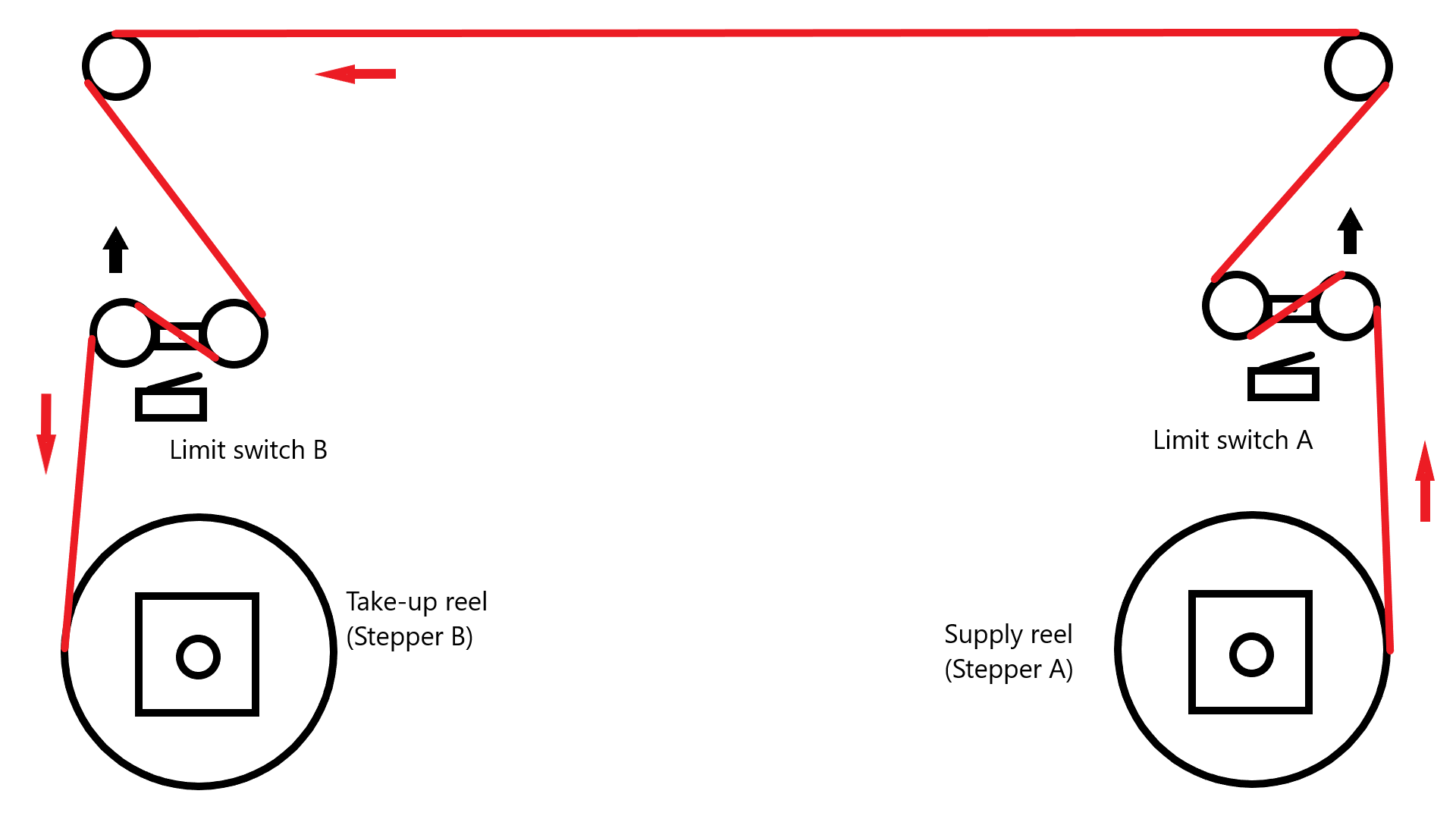
Anyway this setup is basically for keeping tension on the film and also having a rewind option. I have two limit switches that activate when there is tension on the film and then will turn the stepper motor to give some slack. This is for both the supply and take up reels.

There is also rewind button which will rotate the stepper faster to rewind the film after scanning.

Anyway the code kind of works with issues. Currently only one stepper motor will work at a time, but they both need to be able to work at the same time. Also the rewind option will work normally but once limit switch is activated it will start moving slowly.

I might also want to add an IR breakbeam to rewind option so it cannot be activated by mistake and must be a break before it can be activated.

I don't know if my const int are correct or if I should be using #define instead.

Hope this makes sense!

Here is the code below:

/* 
Control "Supply Reel", "Take-Up Reel" and "Rewind Reel" on Raspberry Pi Film Scanner.

Parts used:

  1x Arduino Pro Mini
  2x DVR8825 Driver
  2x Limit Switch
  1x ON/OFF Switch

DVR8825 pinout:
              _________
Enable    <- |  _      | -> Voltage Motor (8,2V - 45V)
M0        <- | |_|     | -> Ground
M1        <- |         | -> B2
M2        <- | DVR8825 | -> B1
Reset     <- |         | -> A1
Sleep     <- |   ___   | -> A2
Step      <- |  |___|  | -> Fault
Direction <- |_________| -> Ground

Stepper motor steps:

MODE0 | MODE1 | MODE2 -> Microstep Resolution
---------------------------------------------
Low   | Low   | Low   -> Full step
High  | Low   | Low   -> Half step
Low   | High  | Low   -> 1/4 step
High  | High  | Low   -> 1/8 step
Low   | Low   | High  -> 1/16 step
High  | Low   | High  -> 1/32 step
Low   | High  | High  -> 1/32 step
High  | High  | High  -> 1/32 step


DRV8825 Driver rotation direction (dirPin):

  HIGH -> Clockwise
  LOW -> Anti-clockwise
  
*/

//Supply Reel DVR8825 Driver Pins (A)

const int stepPin_A = 2;         // Define pin 2 as the steps pin
const int dirPin_A = 3;          // Define pin 3 as the direction pin
const int limitSwitchPin_A = 4;  // Define pin 4 for Limit Switch 1
const int resetPin_A = 5;        // Pin 5 connected to RESET pin
const int M0_A = 6;              // Define pin 6 as "M0"
const int M1_A = 7;              // Define pin 7 as "M1"
const int M2_A = 8;              // Define pin 8 as "M2"
const int rewindSwitchPin_A = 9; // Define pin 9 for Switch for rewind


//Take-up Reel DVR8825 Driver Pins (B)

const int stepPin_B = 10;        // Define pin 3 as the steps pin
const int dirPin_B = 11;         // Define pin 4 as the direction pin
const int limitSwitchPin_B = 12; // Define pin 12 for limit switch 2
const int resetPin_B = 13;       // Define pin 13 connected to reset pin
const int M0_B = 14;             // Define pin 14 as "M0"
const int M1_B = 15;             // Define pin 15 as "M1"
const int M2_B = 16;             // Define pin 16 as "M2"

//Variables will change (switches):

int rewindSwitchState_A = 0;
int limitSwitchState_A = 0; 
int limitSwitchState_B = 0; 


void setup() {
  
  //Supply Reel Setup
  
  pinMode(stepPin_A, OUTPUT);        // Configures "STEP" as output
  pinMode(dirPin_A, OUTPUT);         // Configures "DIR" as output
  pinMode(limitSwitchPin_A, INPUT);  // Configures "limit switch" as input
  pinMode(resetPin_A, OUTPUT);       // Configures reset pin as output
  pinMode(M0_A, OUTPUT);             // Configures "M0" as output
  pinMode(M1_A, OUTPUT);             // Configures "M1" as output
  pinMode(M2_A, OUTPUT);             // Configures "M2" as output
  pinMode(rewindSwitchPin_A, INPUT); // Configures "rewind switch" as input

  //Take-up Reel Setup
  
  pinMode(stepPin_B, OUTPUT);       // Configures "STEP" as output
  pinMode(dirPin_B, OUTPUT);        // Configures "DIR" as output
  pinMode(limitSwitchPin_B, INPUT); // Configures "limit switch" as input
  pinMode(resetPin_B, OUTPUT);      // Configures reset pin as output
  pinMode(M0_B, OUTPUT);            // Configures "M0" as output
  pinMode(M1_B, OUTPUT);            // Configures "M1" as output
  pinMode(M2_B, OUTPUT);            // Configures "M2" as output
  
  }

void loop() { 
  
  // Read the state of the limit switches

  limitSwitchState_A = digitalRead(limitSwitchPin_A);
  limitSwitchState_B = digitalRead(limitSwitchPin_B);
  rewindSwitchState_A = digitalRead(rewindSwitchPin_A);
  
  // If all switches are off do nothing

  if (limitSwitchState_A == LOW && limitSwitchState_B == LOW && rewindSwitchState_A == LOW) {
      digitalWrite(resetPin_A, LOW); 
      digitalWrite(resetPin_B, LOW);
    }

  // If rewind switch is on then rotate anticlockwise 1 full turn (NB. Need to add sensor (IR breakbeam) to detect if film is in correct position)

  else if (limitSwitchState_A == LOW && limitSwitchState_B == LOW && rewindSwitchState_A == HIGH){
    digitalWrite(resetPin_A, HIGH);
    digitalWrite(dirPin_A, HIGH); // Rotate anitclockwise
    digitalWrite(M0_A, LOW);      // Configures the steps division (Full step)
    digitalWrite(M1_A, LOW);      // As above
    digitalWrite(M1_A, LOW);      // As above
    for(int x = 0; x < 200; x++) {
      digitalWrite(stepPin_A, HIGH);
      delayMicroseconds(500);                     
      digitalWrite(stepPin_A, LOW);
      delayMicroseconds(500);
      }
   }

   // If limit switch A is on then rotate anticlockwise 1/32 step

   else if (limitSwitchState_A == HIGH && rewindSwitchState_A == LOW) { 
    digitalWrite(resetPin_A, HIGH);
    digitalWrite(dirPin_A, LOW); // Rotate anticlockwise
    digitalWrite(M0_A, HIGH);    // Configures the steps division (1/32 step)
    digitalWrite(M1_A, HIGH);    // As above
    digitalWrite(M2_A, HIGH);    // As above
    for(int x = 0; x < 200; x++) {
      digitalWrite(stepPin_A, HIGH);
      delayMicroseconds(1000);                      
      digitalWrite(stepPin_A, LOW);
      delayMicroseconds(1000);
      }
    } 

   // If limit switch B is on then rotate clockwise 1/32 step

   else if (limitSwitchState_B == HIGH && rewindSwitchState_A == LOW) { 
    digitalWrite(resetPin_B, HIGH);
    digitalWrite(dirPin_B, HIGH); // Rotate clockwise
    digitalWrite(M0_B, HIGH);     // Configures the steps division (1/32 step)
    digitalWrite(M1_B, HIGH);     // As above
    digitalWrite(M2_B, HIGH);     // As above
    for(int x = 0; x < 200; x++) {
      digitalWrite(stepPin_B, HIGH);
      delayMicroseconds(1000);                      
      digitalWrite(stepPin_B, LOW);
      delayMicroseconds(1000);
      }
    }    
}

This style of programming won't allow both motors to work at the same time

 for(int x = 0; x < 200; x++) {
      digitalWrite(stepPin_A, HIGH);
      delayMicroseconds(1000);                      
      digitalWrite(stepPin_A, LOW);
      delayMicroseconds(1000);
      }

because the FOR loop blocks the Arduino until it completes - and the long delayMicroseconds() are a bad idea also.

You should reorganize your code so there is a variable (perhaps called stepsRemaining) for each motor and every iteration through loop() that is checked and if it is not 0, and if it is time for the next step, the relevant motor is asked to make a single step. Something like this

if (stepsRemainingMotorA != 0) {
   if (micros() - timeLastStepMotorA >= motorAStepInterval) {
        timeLastStepMotorA = micros();
        motorAMove();
        stepsRemainingMotorA -- ;
   }
}
if (stepsRemainingMotorB != 0) {
   if (micros() - timeLastStepMotorB >= motorBStepInterval) {
        timeLastStepMotorB = micros();
        motorBMove();
        stepsRemainingMotorB -- ;
   }
}

Have a look at the second example in this Simple Stepper Code. Note in particular how the step pulse is very short and all the timing is in the interval variable millisBetweenSteps.

...R
Stepper Motor Basics

also look up the AccelStepper library

EDIT to add the lines stepsRemainingMotorA -- ; Sorry for any confusion

Thanks for your reply. I'm a newbie so hopefully I can figure this out! Most of the code I have copied from other examples, but as you have pointed out can't work correctly.

Where would I add the code with variable stepsRemaining?

Do you recommend using the AccelStepper library?

td75:
Where would I add the code with variable stepsRemaining?

FIRST -- I just noted that I omitted a couple of lines from my code - please check the updated version.

I'm no sure what is behind your question. The code I suggested in Reply #1 (or a variation of it) should go in loop(), However I don't know enough about your project to suggest how the value of stepsRemaining should be set or reset.

Do you recommend using the AccelStepper library?

Some people prefer it to writing their own code - especially if the project needs accelerated movement. That may be useful in your case to avoid breaking the film. However the library does require some learning, although the documentation is good. I have not actually used it myself for any of my own projects. And it is not actually that difficult to write your own acceleration code.

...R

Hi,
Welcome to the forum.

Please don't go back and change your code, re-post it with the corrections, this will keep the logical flow of this thread.

Can you please post a copy of your circuit, in CAD or a picture of a hand drawn circuit in jpg, png?

How are you powering your steppers and what are you using to drive them?

Thanks.. Tom.. :slight_smile:

Hi, thank you :slight_smile:

I will get a drawing of circuit done and attach when done.

The stepper motors are being powered by 12 V and using DVR8825 drivers.

I'm still trying to figure out where I should change the code :confused:

td75:
I'm still trying to figure out where I should change the code :confused:

Do your best and if it does not work post your program and tell us exactly what happens when you try it and what you want it to do that is different.

...R

Have attached image of circuit if this helps.

Hi,
Thanks.. OPs circuit;


Tom... :slight_smile:

Hi,
The 5V supply should go into the ProMini at the Vcc pin, not Vraw.
Vraw is for 7 to 12V supplies and connects to the input of internal 5V regulator.

Vcc is the 5V supply rail for the controller.

Make sure the gnd of both supplies are connected together.

Tom.. :slight_smile:

Thanks will do that.

I have tried using the Simple Stepper Code you have linked to, but can't seem to get it working with 2 stepper motors. I just don't have the knowledge to do this at present and trying to make the code as simple as possible to understand.

Anyway have tried changing my code a bit and managed to get it working fine with both steppers running at same time. I have however found there is slight slow down when both steppers are running, which I assume is because of the delay in the code or possibly because of higher power draw?

It does however seem to work fine otherwise and can probably use as is.

If you can however advise where to change the code to work better would really appreciate it :slight_smile:

/* 
Control "Supply Reel", "Take-Up Reel" and "Rewind Reel" on Raspberry Pi Film Scanner.

Parts used:

  1x Arduino Pro Mini
  2x DVR8825 Driver
  2x Limit Switch
  1x ON/OFF Switch

DVR8825 pinout:
              _________
Enable    <- |  _      | -> Voltage Motor (8,2V - 45V)
M0        <- | |_|     | -> Ground
M1        <- |         | -> B2
M2        <- | DVR8825 | -> B1
Reset     <- |         | -> A1
Sleep     <- |   ___   | -> A2
Step      <- |  |___|  | -> Fault
Direction <- |_________| -> Ground

Stepper motor steps:

MODE0 | MODE1 | MODE2 -> Microstep Resolution
---------------------------------------------
Low   | Low   | Low   -> Full step
High  | Low   | Low   -> Half step
Low   | High  | Low   -> 1/4 step
High  | High  | Low   -> 1/8 step
Low   | Low   | High  -> 1/16 step
High  | Low   | High  -> 1/32 step
Low   | High  | High  -> 1/32 step
High  | High  | High  -> 1/32 step


DRV8825 Driver rotation direction (dirPin):

HIGH -> Clockwise
LOW -> Anti-clockwise
  
*/
 
//Supply Reel DVR8825 Driver Pins (A)

const byte stepPinA = 2;         // Define pin 2 as the steps pin
const byte dirPinA = 3;          // Define pin 3 as the direction pin
const byte limitSwitchPinA = 4;  // Define pin 4 for Limit Switch 1
const byte resetPinA = 5;        // Pin 5 connected to RESET pin
const byte M0A = 6;              // Define pin 6 as "M0"
const byte M1A = 7;              // Define pin 7 as "M1"
const byte M2A = 8;              // Define pin 8 as "M2"
const byte rewindSwitchPinA = 9; // Define pin 9 for Switch for rewind

//Take-up Reel DVR8825 Driver Pins (B)

const byte stepPinB = 10;        // Define pin 3 as the steps pin
const byte dirPinB = 11;         // Define pin 4 as the direction pin
const byte limitSwitchPinB = 12; // Define pin 12 for limit switch 2
const byte resetPinB = 13;       // Define pin 13 connected to reset pin
const byte M0B = 14;             // Define pin 14 as "M0"
const byte M1B = 15;             // Define pin 15 as "M1"
const byte M2B = 16;             // Define pin 16 as "M2"

int rewindSwitchStateA = 0;
int limitSwitchStateA = 0; 
int limitSwitchStateB = 0; 

void setup() {

  //Supply Reel Setup
  
  pinMode(stepPinA, OUTPUT);        // Configures "STEP" as output
  pinMode(dirPinA, OUTPUT);         // Configures "DIR" as output
  pinMode(limitSwitchPinA, INPUT);  // Configures "limit switch" as input
  pinMode(resetPinA, OUTPUT);       // Configures reset pin as output
  pinMode(M0A, OUTPUT);             // Configures "M0" as output
  pinMode(M1A, OUTPUT);             // Configures "M1" as output
  pinMode(M2A, OUTPUT);             // Configures "M2" as output
  pinMode(rewindSwitchPinA, INPUT); // Configures "rewind switch" as input

  //Take-up Reel Setup
  
  pinMode(stepPinB, OUTPUT);       // Configures "STEP" as output
  pinMode(dirPinB, OUTPUT);        // Configures "DIR" as output
  pinMode(limitSwitchPinB, INPUT); // Configures "limit switch" as input
  pinMode(resetPinB, OUTPUT);      // Configures reset pin as output
  pinMode(M0B, OUTPUT);            // Configures "M0" as output
  pinMode(M1B, OUTPUT);            // Configures "M1" as output
  pinMode(M2B, OUTPUT);            // Configures "M2" as output
  
}

void loop() {

  // Read the state of all the switches

  limitSwitchStateA = digitalRead(limitSwitchPinA);
  limitSwitchStateB = digitalRead(limitSwitchPinB);
  rewindSwitchStateA = digitalRead(rewindSwitchPinA);

  if (rewindSwitchStateA == HIGH && limitSwitchStateA == LOW && limitSwitchStateB == LOW) {
    digitalWrite(resetPinA, HIGH); // Turn on driver A
    digitalWrite(dirPinA, HIGH);   // Rotate clockwise  
    digitalWrite(M0A, LOW);        // Configures the steps division (Full step)
    digitalWrite(M1A, LOW);        // As above
    digitalWrite(M2A, LOW);        // As above 
    singleStepRewindA();
  } 
  if (limitSwitchStateA == HIGH) {
    digitalWrite(resetPinA, HIGH); // Turn on driver A
    digitalWrite(dirPinA, LOW);    // Rotate anticlockwise 
    digitalWrite(M0A, HIGH);       // Configures the steps division (1/32 step)
    digitalWrite(M1A, HIGH);       // As above
    digitalWrite(M2A, HIGH);       // As above 
    singleStepA();
  } 
  if (limitSwitchStateB == HIGH) {
    digitalWrite(resetPinB, HIGH); // Turn on driver
    digitalWrite(dirPinB, LOW);   // Rotate anticlockwise 
    digitalWrite(M0B, HIGH);       // Configures the steps division (1/32 step)
    digitalWrite(M1B, HIGH);       // As above
    digitalWrite(M2B, HIGH);       // As above 
    singleStepB();
  }   
}

void singleStepRewindA() {
  digitalWrite(stepPinA, HIGH);
  delayMicroseconds(500);
  digitalWrite(stepPinA, LOW);
  delayMicroseconds(500);
}

void singleStepA() {
  digitalWrite(stepPinA, HIGH);
  delayMicroseconds(500);
  digitalWrite(stepPinA, LOW);
  delayMicroseconds(500);
}

void singleStepB() {
  digitalWrite(stepPinB, HIGH);
  delayMicroseconds(500);
  digitalWrite(stepPinB, LOW);
  delayMicroseconds(500);
}

td75:
I have tried using the Simple Stepper Code you have linked to, but can't seem to get it working with 2 stepper motors.

Without seeing the code where you tried to get it working I cannot offer advice.

I agree that the delayMicroseconds() in your code in Reply #11 is probably the cause of the slowing down. The second example in my Simple Stepper Code uses non-blocking code.

...R

This is what I have tried...

//Supply Reel DVR8825 Driver Pins (A)

byte stepPinA = 2;         // Define pin 2 as the steps pin
byte dirPinA = 3;          // Define pin 3 as the direction pin
byte limitSwitchPinA = 4;  // Define pin 4 for Limit Switch 1
byte resetPinA = 5;        // Pin 5 connected to RESET pin
byte M0A = 6;              // Define pin 6 as "M0"
byte M1A = 7;              // Define pin 7 as "M1"
byte M2A = 8;              // Define pin 8 as "M2"
byte rewindSwitchPinA = 9; // Define pin 9 for Switch for rewind

//Take-up Reel DVR8825 Driver Pins (B)

byte stepPinB = 10;        // Define pin 3 as the steps pin
byte dirPinB = 11;         // Define pin 4 as the direction pin
byte limitSwitchPinB = 12; // Define pin 12 for limit switch 2
byte resetPinB = 13;       // Define pin 13 connected to reset pin
byte M0B = 14;             // Define pin 14 as "M0"
byte M1B = 15;             // Define pin 15 as "M1"
byte M2B = 16;             // Define pin 16 as "M2"

boolean rewindSwitchAPressed = false;
boolean limitSwitchApressed = false;
boolean limitSwitchBpressed = false;

unsigned long curMillis;
unsigned long prevStepMillis = 0;
unsigned long millisBetweenSteps = 25; // milliseconds

void setup() {

  //Supply Reel Setup
  
  pinMode(stepPinA, OUTPUT);        // Configures "STEP" as output
  pinMode(dirPinA, OUTPUT);         // Configures "DIR" as output
  pinMode(limitSwitchPinA, INPUT);  // Configures "limit switch" as input
  pinMode(resetPinA, OUTPUT);       // Configures reset pin as output
  pinMode(M0A, OUTPUT);             // Configures "M0" as output
  pinMode(M1A, OUTPUT);             // Configures "M1" as output
  pinMode(M2A, OUTPUT);             // Configures "M2" as output
  pinMode(rewindSwitchPinA, INPUT); // Configures "rewind switch" as input

  //Take-up Reel Setup
  
  pinMode(stepPinB, OUTPUT);       // Configures "STEP" as output
  pinMode(dirPinB, OUTPUT);        // Configures "DIR" as output
  pinMode(limitSwitchPinB, INPUT); // Configures "limit switch" as input
  pinMode(resetPinB, OUTPUT);      // Configures reset pin as output
  pinMode(M0B, OUTPUT);            // Configures "M0" as output
  pinMode(M1B, OUTPUT);            // Configures "M1" as output
  pinMode(M2B, OUTPUT);            // Configures "M2" as output
  
}

void loop() {

  curMillis = millis();
  readButtons();
  actOnButtons();
  
}

void readButtons() {

  rewindSwitchAPressed = false;
  limitSwitchApressed = false;
  limitSwitchBpressed = false;

  if (digitalRead(rewindSwitchPinA) == HIGH) {
    rewindSwitchAPressed = true;
  }
  if (digitalRead(limitSwitchPinA) == HIGH) {
    limitSwitchApressed = true;
  }
  if (digitalRead(limitSwitchPinB) == HIGH) {
    limitSwitchBpressed = true;
  }
  
}

void actOnButtons() {
  
  if (rewindSwitchAPressed == true && limitSwitchApressed == false && limitSwitchBpressed == false) {
    digitalWrite(resetPinA, HIGH); // Turn on driver A
    digitalWrite(dirPinA, HIGH);   // Rotate clockwise  
    digitalWrite(M0A, LOW);        // Configures the steps division (Full step)
    digitalWrite(M1A, LOW);        // As above
    digitalWrite(M2A, LOW);        // As above 
    singleStepA();
  }
  if (limitSwitchApressed == true) {
    digitalWrite(resetPinA, HIGH); // Turn on driver A
    digitalWrite(dirPinA, LOW);    // Rotate anticlockwise 
    digitalWrite(M0A, HIGH);       // Configures the steps division (1/32 step)
    digitalWrite(M1A, HIGH);       // As above
    digitalWrite(M2A, HIGH);       // As above 
    singleStepA();
  }
  if (limitSwitchBpressed == true) {
    digitalWrite(resetPinB, HIGH); // Turn on driver
    digitalWrite(dirPinB, LOW);    // Rotate anticlockwise 
    digitalWrite(M0B, HIGH);       // Configures the steps division (1/32 step)
    digitalWrite(M1B, HIGH);       // As above
    digitalWrite(M2B, HIGH);       // As above 
    singleStepB();
  }
  
}

void singleStepA() {
  
  if (curMillis - prevStepMillis >= millisBetweenSteps) {
    prevStepMillis = curMillis;
    digitalWrite(stepPinA, HIGH);
    digitalWrite(stepPinA, LOW);   
  }
  
}

void singleStepB() {
  
  if (curMillis - prevStepMillis >= millisBetweenSteps) {
    prevStepMillis = curMillis;
    digitalWrite(stepPinB, HIGH);
    digitalWrite(stepPinB, LOW);   
  }
  
}

td75:
This is what I have tried...

And what happens when you run the program and what do you want it to do that is different?

I think I would keep the tests for the limit switches separate from the tests for the the rewind situation. If a limit switch is triggered it means the system has reached a certain state - i.e. you know where the motor has got to. I know there is a degree of duplication if you have a variable called (for example) motorAtA which would be set to true when the limit switch is triggered but I think it is justified by making the logic clearer. if motorAtA == true then something needs to happen. When that something happens (i.e. motor starts moving towards B) it will probably set motorAtA back to false even though the limit switch may still be triggered.

...R

Robin2:
And what happens when you run the program and what do you want it to do that is different?

Only one stepper will move at a time - they both need to move simultaneously if limit switches are activated. Also when the stepper moves it's very slow/jerky.

Both steppers work in code shown in reply #11 but with slow down.

I think I would keep the tests for the limit switches separate from the tests for the the rewind situation. If a limit switch is triggered it means the system has reached a certain state - i.e. you know where the motor has got to. I know there is a degree of duplication if you have a variable called (for example) motorAtA which would be set to true when the limit switch is triggered but I think it is justified by making the logic clearer. if motorAtA == true then something needs to happen. When that something happens (i.e. motor starts moving towards B) it will probably set motorAtA back to false even though the limit switch may still be triggered.

Not sure how to keep tests separate? I have in the meantime removed the rewind option and only using the two limit switches, but still only one stepper moves at a time.

Do you have an example code using millis() for two steppers working simultaneously?

I am confused,

First, without turning off the “reset” pin, the driver is going to try to “keep” that stepper motor in that exact arc.

So if your other stepper motor is pulling on it (any direction), it’s a tug of war between the two motors and the result will be full step “jerks” no matter what microsteping value it’s set at.

Second, the rotation speed of two reels winding a tape between them will vary as the tape buildup on the reel adjusts the “gear ratio” between them. Even with a encoder tracking, it would be very difficult to control two stepper motors working together without the same “tug of war” game playing out and creating ripple strain all along your tape.

Slumpert:
I am confused,

First, without turning off the “reset” pin, the driver is going to try to “keep” that stepper motor in that exact arc.

So if your other stepper motor is pulling on it (any direction), it’s a tug of war between the two motors and the result will be full step “jerks” no matter what microsteping value it’s set at.

When should I turn off the "reset" pin in the code?

Slumpert:
Second, the rotation speed of two reels winding a tape between them will vary as the tape buildup on the reel adjusts the “gear ratio” between them. Even with a encoder tracking, it would be very difficult to control two stepper motors working together without the same “tug of war” game playing out and creating ripple strain all along your tape.

There are tensioners on supply and take-up reel so this isn't a problem. As there is more tension the limit switch is activated, stepper turns and reduces tension.

Perhaps this will make it clearer to understand. There is actually a third stepper motor with film sprocket but this is controlled by the raspberry pi so not shown in image attached.

To turn off the driver, just set the resetpin low again after the step, your already turning it on every step.

Picture helps alot

I think the original code was better suited for this, your “tried” code and it’s 25ms delay between steps seems wrong considering the limitswitches are the feedback control, not time.