I made a some research, sorry if I ask some obvious questions but I am completely new to this...
Would the IRF520 work for this?
I've even found it already pre-soldered to some board which are sold specifically for Arduino so my polite guess it posivite about it...just wanted a confirmation...
OMG, sorry, you are right, the IRF520 is exactly what I have, I was convinced, I don't know how, that I had the 540...
Maybe a stupid question...
But why, even in the Arduino starter pack, they provide the IRF520 if they cannot be driven properly by Arduino?
Also, how can they sell those module if Arduino cannot open the gate 100%?
Thank you for the hint about the 30N06L, but apparently it doesn't exist on Italian Amazon...any other suggestion?
Thank you for the scheme! The fans MUST be in series or they could also be in parallel?
Yes, you can use a BJT. Just make sure it can handle your voltage (24V) and the current demand (plus margin) Since you have 180mA x 3 = 480mA, a 1A BJT will work just fine. Look for "Darlington Pair" to make sure you can handle the current (common types are TIPxxx)
In series, each fan will not get a full 24v. The voltage to each fan will be divided evenly among the fans plus any circuit resistances.
I would advocate for parallel connection. One of the reasons is that if a fan fails or begins to fail, the other two fans will be affected too. Vice in parallel, the fans will operate independently.
Another reason is that they should run faster, which may not be necessary in your case. See attached pic and note the higher current to each fan in parallel config, plus a full 24v to each fan.
thank you for your explanation and scheme!
I actually put the fans in parallel (without knowing exactly the reason why but I thought it was better: I knew about the fact that if one failed the other ones would too, in series, but I didn't know about the dropping volts...).
Thanks for the transistor name!
Unluckily even this one is not available on amazon.it... very strange I cannot find anything at logical level!
The mistery remains for me about why Arduino provides the IRF520 in the starter pack if they cannot be controlled properly...
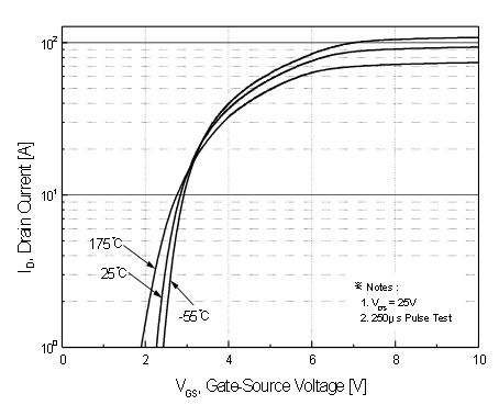
according the datasheet Vgs threshold it could be anywhere from 2V to 4V (guaranteed threshold) which means somewhere between this value you should be able to conduct 250 uA
Due to this manufacturing tolerance... it may work or it may not work at 4V ( I don't count 250 uA as working)
Note how they are performing the test: 20 uS pulse width - sounds like a single pulse. It's 20/1,000,000 th of a second.
Even if you were to pass 2A with 5V at gate. you have no idea what the Rds is so while it may pass 2A but for how long and how hot will the MOSFET get? They have done all the Rds rating at 10V Vgs because I'm sure it's not great at 5V and it was really designed for higher voltage switching. Notice also that the gate voltage goes up exponentially.
I estimate a reasonable Rds for 5V is about 2-3 Ω (it's 0.25 Ω or 250 mΩ at 10V)
I believe if you switched 24V 2A we are talking about dropping about 4-6 volts at the mosfet... that's going to get hot dissipating 8-12 watts. Wasting power and getting hot!
It will also reduce the voltage going to your fan which it probably needs.
There are a number of other issues including switching speed and other inefficiencies.
the specs for the 30N06L is better for logic levels.
Why keep insisting that it will work... it's like using the wrong tool for the job. There are better mosfets out there for our logic level switching which will work better, waste less power and I highly recommend saving the IRF520 and 540 for when you need something that has higher gate voltage.
darrell hope the information helps, was hoping to just clarify the issue. Yes it will switch, and if the current is low enough you might be ok. But be careful with the datasheets... there's some marketing involved with those specs.
these are in the TO220 packages everyone seems to be familiar with - easy to breadboard
IRLB8721
IRL520
IRL520
IRL540
IRL640
IRL3803
the list goes on and on...
Quick search in Digi-Key gives you over 54,000 choices for MOSFETs... no one knows them all.
He was using the IRF520 - wasn't working... and now we keep pushing him back to IRF520. You could drive it with a transistor but it's not easy.
If you use one transistor it would stay on at power off because it needs a pull up. We have the wrong MOSFET yet again... it has to be done with a P-CHANNEL.
Another option is to use two transistors. but it really starts to get messy. The OP needs to get the right device to do this correctly.
To me the IRL520 looks like an N-channel logic MOSFET and it ought to work. Either the item is damaged, not connected the proper way or something else is wrong. Lets spot what is wrong.
Helpers could use their time in a more productive way than just moving around the spoon in the kettel. Adding new guesses is waisting brain energy as I feel. It's like keeping a communication running in idle without adding anything solving the problem.
Yes, it's free to leave the topic but what about OP wanting the problem to get solved?