Hi,
I've been trying to find where I have gone wrong with my fan wiring as everything was working properly and then I moved some wires that didn't involve the fans but must have moved something by mistake.
I have an Arduino Due controlling a LR7843 logic level Mosfet board to turn on 12V Noctua 4 wire fan and it was working properly 2 years ago but I added some sensors and somehow messed up the wiring so I'm trying to put everything back to the way it was and can't seem to find my wiring diagram from 2 years ago.
I was using a temp sensor to turn it on and off and the temp sensor works properly but it doesn't turn the fan off, it just continuously runs. I have a digitalWrite in the setup to turn the fan off on startup but the fan ignores it and stays on.
The Mosfet board inverts the logic so High's are Low's and vice versa.
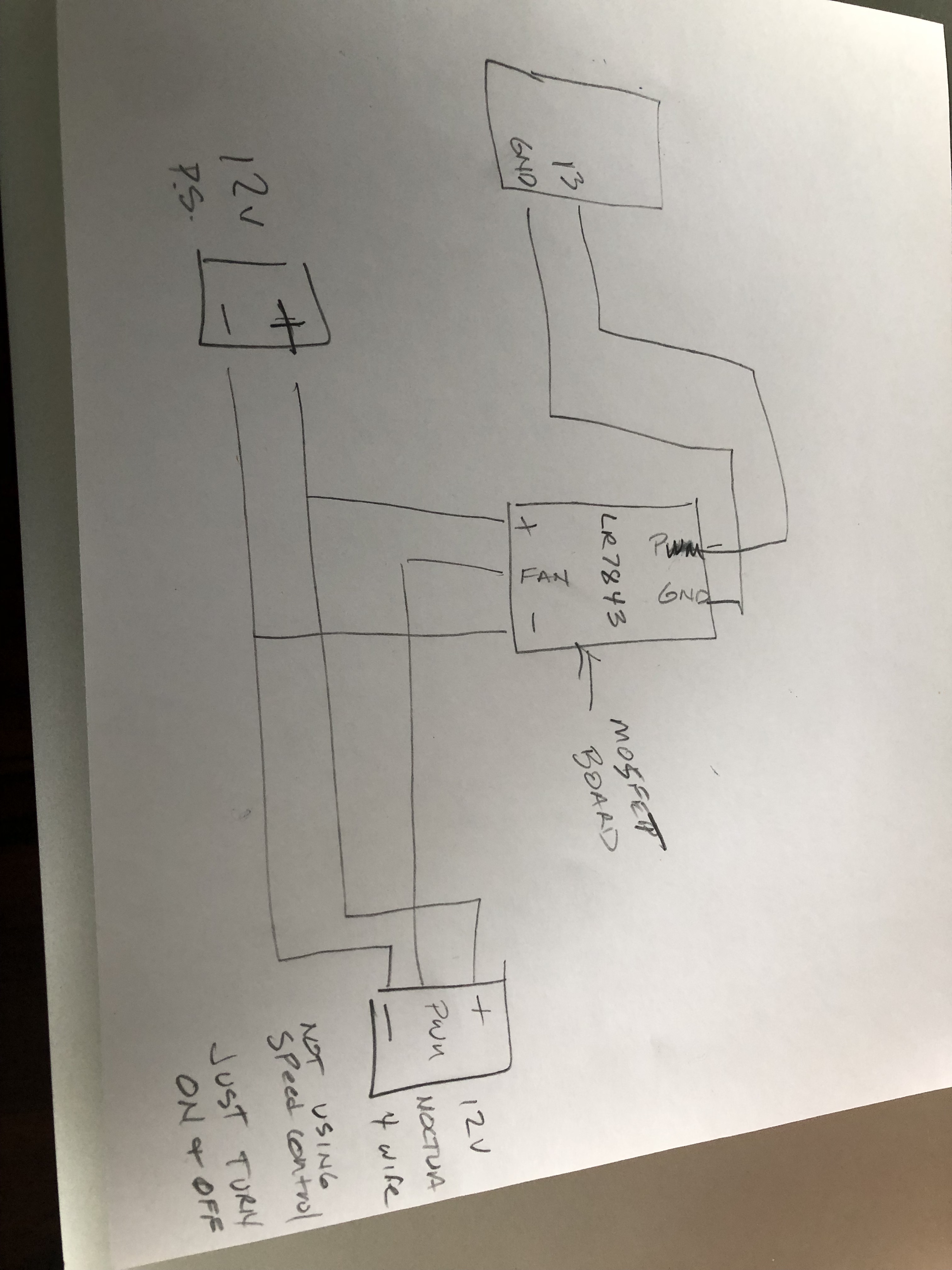
Here is how I have it wired,
#include <Wire.h> // Used to establish serial communication on the I2C bus
#include <SparkFun_TMP117.h> // Used to send and recieve specific information from our sensor

// The default address of the device is 0x48 (GND)
TMP117 sensor; // Initalize sensor


byte AlertFlag = 0; //variable to hold high and low alert flags from configuration register
boolean H_AlertFlag = 0;  //variable to hold state of high alert flag
boolean L_AlertFlag = 0;  //variable to hold state of low alert flag

unsigned long startMillis;
unsigned long currentMillis;
const unsigned long period = 1500;

unsigned long startMillis2;
unsigned long currentMillis2;
const unsigned long period2 = 500;


void setup()
{
  pinMode(13, OUTPUT);
  digitalWrite(13, HIGH);
  Wire.begin();
  Serial.begin(115200);    // Start serial communication at 115200 baud
  Wire.setClock(400000);   // Set clock speed to be the fastest for better communication (fast mode)

  if (sensor.begin() == true) // Function to check if the sensor will correctly self-identify with the proper Device ID/Address
  {
    Serial.println("Begin");
  }
  else
  {
    Serial.println("Device failed to setup- Freezing code.");
    while (1);
  }
  sensor.setHighLimit(60); //set high limit to 25.50°C
  sensor.setLowLimit(35 );  //set low limit to 25.00°C
  sensor.setAlertFunctionMode(0);//set to alert mode

}


void loop()

{
  if (sensor.dataReady() == true) // Function to make sure that there is data ready to be printed, only prints temperature values when data is ready

    unsigned long currentMillis = millis();
  {
    currentMillis = millis();
    if (currentMillis - startMillis >= period)
      startMillis = currentMillis;

    AlertFlag = sensor.getHighLowAlert(); //read the alert flags from the configuration register
    H_AlertFlag = bitRead(AlertFlag, 1); //grab the high alert field using bitwise operator and save current to H_AlertFlag
    L_AlertFlag = bitRead(AlertFlag, 0); //grab the low alert field using bitwise operator and save current L_AlertFlag

    if (H_AlertFlag == true)
    {
      digitalWrite(13, LOW);
    }
    else if (L_AlertFlag == true)
    {
      digitalWrite(13, HIGH);
    }
    unsigned long currentMillis2 = millis();
    {
      currentMillis2 = millis();
      if (currentMillis2 - startMillis2 >= period2)
        startMillis2 = currentMillis2;
    }
  }
}
little autoformat, check if you really wanted all that lines or it was typo
#include <Wire.h> // Used to establish serial communication on the I2C bus
#include <SparkFun_TMP117.h> // Used to send and recieve specific information from our sensor

// The default address of the device is 0x48 (GND)
TMP117 sensor; // Initalize sensor

byte AlertFlag = 0; //variable to hold high and low alert flags from configuration register
boolean H_AlertFlag = 0;  //variable to hold state of high alert flag
boolean L_AlertFlag = 0;  //variable to hold state of low alert flag

unsigned long startMillis;
unsigned long currentMillis;
const unsigned long period = 1500;

unsigned long startMillis2;
unsigned long currentMillis2;
const unsigned long period2 = 500;

void setup(){
  pinMode(13, OUTPUT);
  digitalWrite(13, HIGH);
  Wire.begin();
  Serial.begin(115200);    // Start serial communication at 115200 baud
  Wire.setClock(400000);   // Set clock speed to be the fastest for better communication (fast mode)

  if (sensor.begin() ) // Function to check if the sensor will correctly self-identify with the proper Device ID/Address
    Serial.println("Begin");
  else  {
    Serial.println("Device failed to setup- Freezing code.");
    while (1);
  }
  sensor.setHighLimit(60); //set high limit to 25.50°C
  sensor.setLowLimit(35 );  //set low limit to 25.00°C
  sensor.setAlertFunctionMode(0);//set to alert mode
}

void loop() {
  // Function to make sure that there is data ready to be printed, only prints temperature values when data is ready
  if (sensor.dataReady())unsigned long currentMillis = millis();
  currentMillis = millis();
  if (currentMillis - startMillis >= period)startMillis = currentMillis;

  AlertFlag = sensor.getHighLowAlert(); //read the alert flags from the configuration register
  H_AlertFlag = bitRead(AlertFlag, 1); //grab the high alert field using bitwise operator and save current to H_AlertFlag
  L_AlertFlag = bitRead(AlertFlag, 0); //grab the low alert field using bitwise operator and save current L_AlertFlag

  if (H_AlertFlag )digitalWrite(13, LOW);
  else if (L_AlertFlag )digitalWrite(13, HIGH);

  unsigned long currentMillis2 = millis();
  currentMillis2 = millis();
  if (currentMillis2 - startMillis2 >= period2)startMillis2 = currentMillis2;
}
You have the fan power leads connected directly to 12V and the MOSFET in the PWM signal line. Are you trying to control fan speed or just switch it ON/OFF/
HI, @1ribbonman
Write some simple code to turn the Arduino output 13 on and off for 5 seconds at a time and see if the module operates.
Put nothing else in your code, just the output actuation.
Without PWM terminal connected the fan should run full speed,
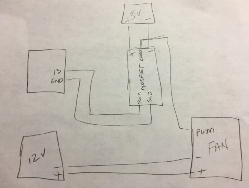
Connect 12V and MOSFET like this, the diode is needed to protect the MOSFET from back EMF.
Hi, @1ribbonman
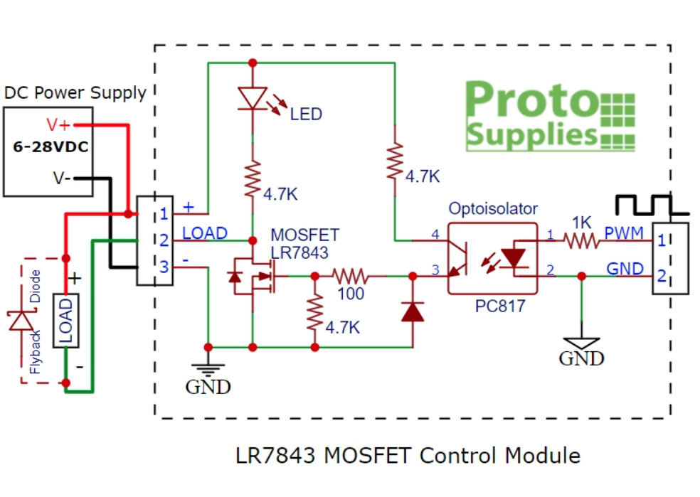
Don't forget the Due is only 3V3 output logic.
The PC817 on the module needs about 20mA to reliably operate the opto.
The module uses 1K series resistor so;
I = V / R = 3V3 / 1000 = 3.3 mA.
I would say not enough current, the spec of the opto may have drifted in 2years to where the LED current is not sufficient to operate the opto.
If you can, measure the voltage across the 1K resistor when activated.
I do have a DMM.
On post#10 you are using the wrong diagram, sorry about that.
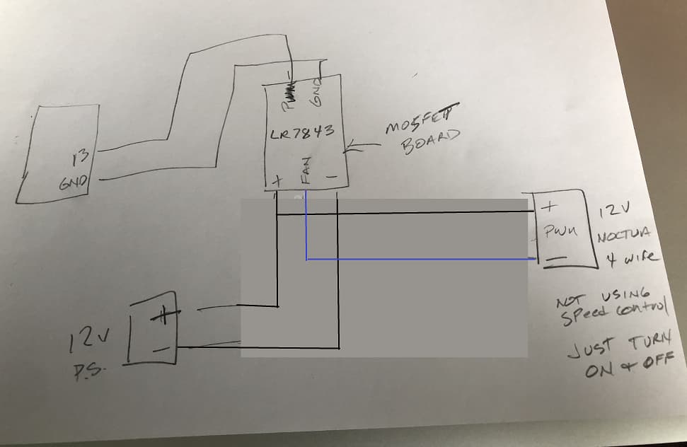
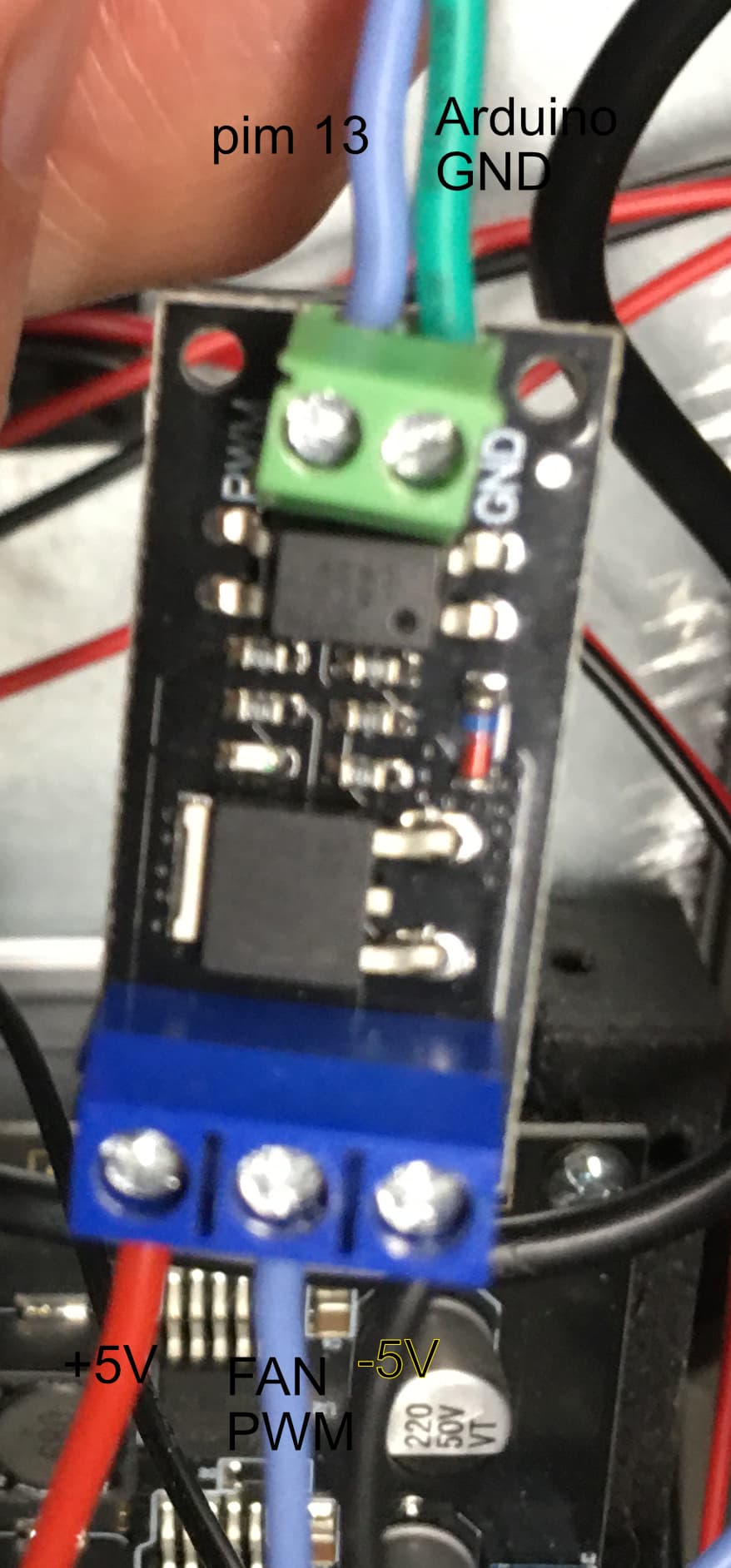
here's a photo of the connections on the Mosfet, The 12V lines go directly to the Fan.
it's hard to read the text on the black wire on the bottom of the Mosfet but it says -5V next to the light blu PWM wire.
I realize the logic problem which is why the Mosfet is being used, the LR7843 is supposed to work on 3v3.
It did work when I first hooked it up, on startup the fan would turn off and when the Temp got to a certain level the fans would turn on and when it cooled enough they would turn off.