Im quasi-new to this sort of thing, and i'm doing my best to learn things, so please bare with me.
I've recently jumped onto a project called iAqua, and it has many things going on, most of which I understand by now, but there is one thing that im hung up on; PWM LED lighting.
This is the shield I will be using on an arduino mega 2560 r3;
At the top-center there is a pin-out for PWM control, but I can't figure out how to wire it. The Arduino board certainly cant provide power directly because the LED strip pulls 24V 3A, so it will have to draw from an external source.
Would one of these work in conjunction with the arduinos output?
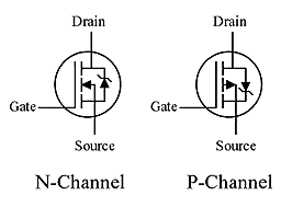
You can drive a ‘Logic Level MOSFET’ with the output.
Use circuit C1.
M3 and D3 would be removed and you then connect your LED pin to the MOSFET drain.
Also, R28 would not be needed (replace it with a piece of wire) as you have a 220R on your shield already.
So if i'm reading it right, on each channel;
From arduino pin there is a 220 ohm resistor which leads to the gate on a mosfet and also to a grounded 10k ohm resistor. The mosfet source is grounded, and the mosfet drain connects to the LEDstrips R/G/B/W cathode pin. The LEDstrips shared anode pin goes straight to powersource which is +24VDC.
Did I get that correct?
I'm also still curious if this device can do it as well, as it is easier and more compact than having to make something myself.
Sorry, I should have clarified, the virtual breadboard software im using is a little hokey and doesn't have mosfet objects for some reason, so I grabbed the nearest thing.
Could you tell if this device would work?
It would be easier and smaller and probably cheaper than making something myself.
W B R G wires would probably be switched outputs, i.e. switched +24v.
These would go to the LED anodes, therefore you need a strip the has common cathodes as there is a black (probably GND) wire which should connect to all the cathodes.
Please confirm if your strip is common cathode or common anode.
Edit:
It say "Connecting Mode: Common anode (or common cathode)"
I cannot verify what this means in their context.
They do not say if it is compatible with 5V logic (Arduino).
You might want to stick with designing an interface as per your actual hardware.
The blue things are supposed to represent the mosfets,
the horizontal block terminal is supposed to be a barrel jack socket,
my drafting software didn't have those.
Its about 4 times as expensive and 4 times as large as that ebay amplifier, but better safe than sorry I suppose.
EDIT :
I got a reply from one of the eBay vendors about the question if input can be 5v while output is 24v, they said yes. So now im conflicted a bit. :') I guess I could risk it for a biscuit and order an ebay amplifier, to hook up to a cheap 24v PSU I have laying around, and see what pins it comes out of. I assume it should technically only go out to the common anode pin, and only on the output side.
Black is common anode, at least according to LED strip standards.
The colors never really correspond to the strips, I guess its just how ribbon cable is colored.
I've ordered one and I shall do some experimenting when I get it.
First ill just stick 24v on the power leads to see where it comes out of.
Then ill just run a cheap LED controller on 5v on the input and a bit of 24v strip on the output.
If that works, it should mean its good to go for the arduino as well, right?
Sokonomi:
Black is common anode, at least according to LED strip standards.
That is somewhat confusing, but of course if you use red, green and blue wires for the colours, you tend to use black for the common. It should actually be white for the positive, given a choice.