For a project, I want to individually control the speed of 25 dc motors. The change in speed does not have to be precise and can just be low, medium, and high speed. I also do not want to control the direction of rotation only the speed (so no need for a h-bridge). The motors I am using are 3-6V and 0.35-0.4A.
So my idea was to simply use the PWM pins of the Arduino. However of course the Arduino does not have enough pin inputs thus to solve this I bought two of the "adafruit 16-channel 12-bit pwm" so I can stack them and create all the necessary inputs. However the current on the PWM pins is not sufficient to drive a DC motor directly. And the channels have no kickback protection diodes. But I can still use the PWM output to control a transistor circuit.
Although I am fairly okay with programming all the motors I am not confident at building and figuring out what is the best circuit (eg what kind of power supply do I need, what transistors to use). Especially building such a big setup is kind of a first for me. Does anyone have experience with connecting this much dc motor to an Arduino? If so, would you have any tips about what and what not to do....
It is always good to separate the Arduino board from so many outputs, so you can exchange and repair it more easily.
Can you give a link to those motors ?
The 0.35 to 0.4A does not tell much. What is the stall current ?
A mosfet is the best choice, but normal transistors is also okay.
You would need a "logic level" mosfet, a flyback/kickback diode and two resistors per motor.
There are modules with mosfet outputs and there might be chips with a few mosfets.
Tips: Grounding (where do the ground currents go)
Grounding is a craftsmanship on its own.
Suppose that 25 motors use 0.4A, then you have 10A. That current is going through the motors and then into the GND wire and back to the power supply. That current can disturb the Arduino board.
Can you give a broader view on your project ? What is your project ? Will the motors be far apart ?
Since you are not that experienced in hardware building, you can buy MOSFET PWM drive modules, they would be wired between the motors and the Adafruit board(s).
I am using them as vibrating motors so I added weight to the dc motors to they become unbalanced. Then they will be added to a wooden frame to basically make a DIY vibratory tumbler machine. This whole setup is 10 x 10 cm. I will repeat this 25 times. They will then be placed to create a 5 by 5 grid so the motors will have a distance of about 8 cm from each other.
The easiest and simplest circuit that I found was the following:
Would this be a good one to replicate for all the motors?
I also looked into using motor drivers however because I do not need to change the direction of the rotation speed I felt like this would only cost me more money.
Yes I would also want an OFF speed. I will pre-program the speeds and create different "patterns" for them so one is at high speed, one is off and one is at low speed etc.
Nope for now it is a prototype and it will be more of a proof of concept I will already have my hands-full with building the installation thus the less programming the better
I see two large power supplies for the motors. 3 volts and 6 volts. I see two relays per motor. One relay for 3 volts. One relay for 6 volts. When both relays are off, the motors are off. This should get you going on your proof of concept.
You could do it with two PCA9685 16-Channel 12-Bit PWM Servo Motor Drivers , 25 logic level avalanche rated MOSFETS. Assuming you do not care at reset what the motors are doing that would do it, if you are concerned you will also need pull down resistors for the PCA9685 port pins. You would use the PWM output pins to drive your MOSFET gates. Avalanche rated MOSFETs will not need a flyback diode. This can be done with any arduino that supports I2C. Here is a link for some informaiton. https://cdn-learn.adafruit.com/downloads/pdf/16-channel-pwm-servo-driver.pdf
There is another part that will reduce the amount of wiring you have to do, it is a Integrated Serial-Controlled Solenoid and Motor Driver MAX2220.
@anotherone1234 1. You have 25 motors and you want to control their speeds individually; so, you need 25 PWM signals and 25 IR Speed Measuring Sensors -- is it correct?
2. If Section-1 is correct, then you can use the following ESP32S Board (Fig-1) for generating 25 PWM signals which can be fed to the Motor Terminals via L298N-based Motor Drivers (Fig-2)
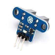
3. Next issue will come as to to knowing the current speed of the individual motors for which you can use the following 25xIR Speed measuring Sensors (Fig-3).
Figure-3: IR Sensor
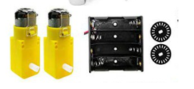
Figure-3: 3V - 6V Motor with Encoder Disc
4. The next issue is to collecting signals from the IR Sensors and passing them to the ESP32S Board of Fig-1 for modulating the duty cycles of the PWM signals.
...pending
I don't think @anotherone1234 needs that. It would be an unnecessary complication.
Two power supplies and 50 relays can't be the easiest way, surely?
True, but did you know that, provided only single direction is needed, most H-bridge chips can drive 2 motors? A dual H-bridge chip can drive 4 motors. This might be easier than using individual transistors. It's something to consider.
This type of motor driver will have a large voltage drop, around 2V, so @anotherone1234 would need to increase the power supply to compensate. Motor drivers with more modern designs and lower voltage drops are available. Individual MOSFETs might be a better solution, more components and soldering to be done, but maybe cheaper and more convenient, and heat dissipation should not be a problem.