I'm learning how to have two boards to communicate with an uno controlling a nano.
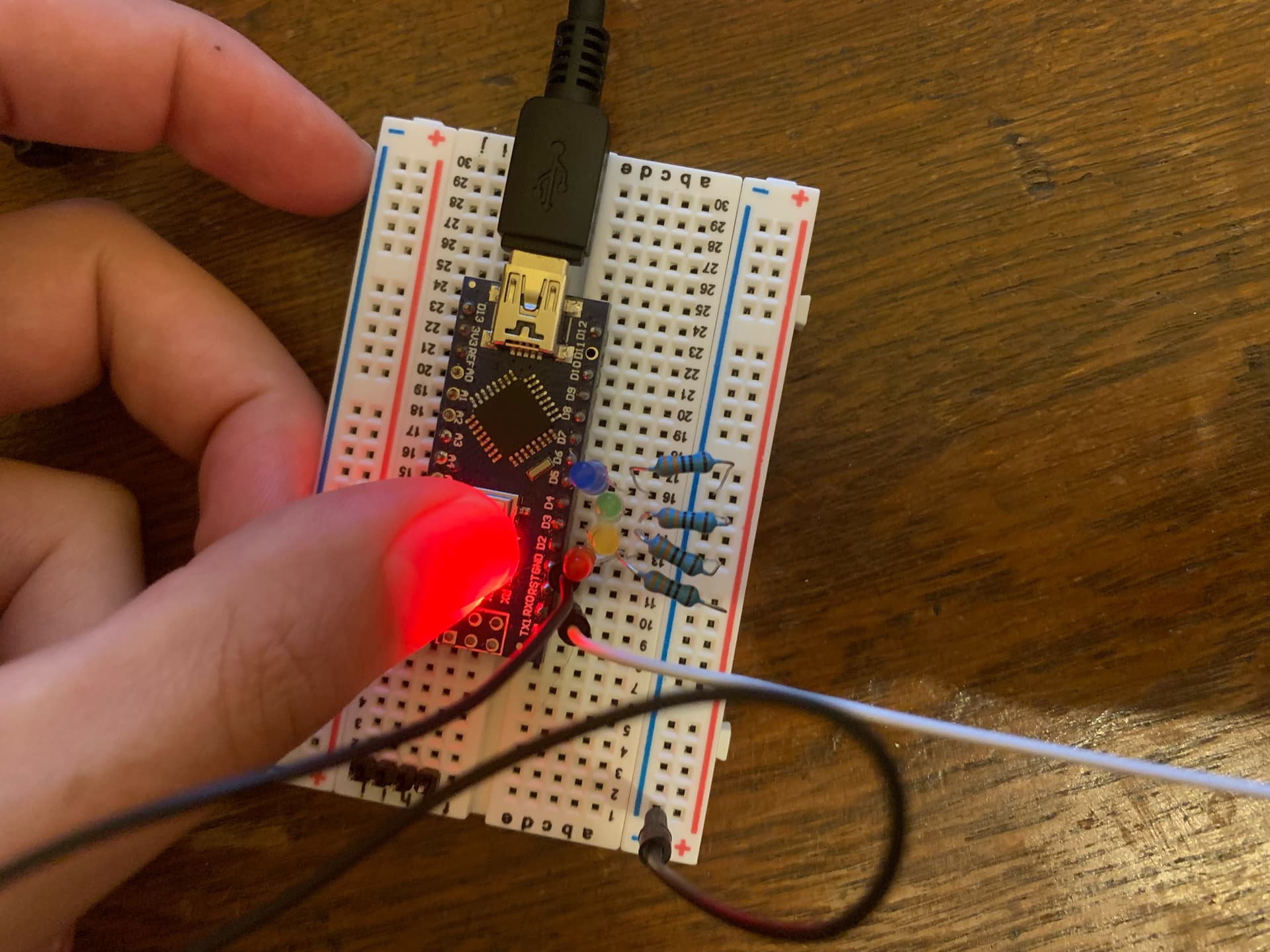
I have 4 switches on the uno and four LEDs on the nano.
I am trying to use arrays to set up and control the LEDs and switches.
When I press the buttons, the RX light on the nano lights up. So it's receiving data. But I can't get the LEDs to light up.
Here is the code for the transmitter:
//Transmitter

int button[4]={2,3,4,5};
int buttonstate;
int i;

void setup() {
  Serial.begin(9600);
  for(i=0;i<4;i++){
    pinMode(button[i],INPUT_PULLUP);
  }
}

void loop() {

for(i=0;i<4;i++){
  if(digitalRead(button[i])== LOW){
    Serial.println(button[i]);
    delay(10);
  }
}
}
You're sending the values using Serial.println.
That sends the ASCII value of the number, and then adds on a carriage-return and line-feed characters, but your receiver code doesn't do anything about these character.
Also your for loops are no synchronised.
I am very new to this so a lot of the terminology and pointing out the problems is lost on me. Any help on explaining why and the mechanics of it would be hugely appreciated!
But thank you for your replies so far!
I'm familiar with ASCII but I dont know what you mean by carriage return etc. And I have no idea what you mean by my for loops not being synchronised
Back in the "olden days" when typewriters were used they had a lever on them that moved the paper up ready to type on the next line (a linefeed) and moved the print carriage back to the start of the line ( a carriage return). When printers were invented the same terminology was used to describe the same actions, ie move to next line and move to start of line and there are ASCII characters specially dedicated to this meaning
In the Arduino Serial monitor you can set the Line ending to be either of these two special characters, both of them or none and they will be added automatically to the user input. They can then be detected by the sketch so that it knows that the end of the input has been reached, but if you have told the Serial monitor to add them then you must allow for them when reading the Serial input as they will be available() and will be read and processed by your sketch. Set the Line ending to none and they won't be sent
I mean that there is nothing in the data transmitted that says the first item is meant for the first LED, the second item for the second LED and so on.
In the receiver, a for loop checks to see if there's a character available to read. If there isn't (and most of the time there won't be), the for loop moves on to the next LED.
Then the for loop terminates, loop() returns, and gets called again, so the for loop starts over, and again, mostly it will finish without ever reading a character, because serial I/O is sloooooow.
Even if you do read a value, you have a one in four chance of writing it to the correct LED.
A better approach might be to send, say 'a' to turn off the first LED, and 'A' to turn it on, 'b' to turn off the second LED and 'B' to turn it on, and so on.
1. The command Serial.println() is composed of the following two commands:
Serial.write(0x0D); //0x0D (0x refers to hex base) is the ASCII code for CR (Carriage Return)
Serial.write(0x0A); //0x0A is the ASCII code for line-feed (LF)/Newline(NL)
When Serial.prinln('2'); is executed (for example), then the following 3-bytes ASCII coded data are transmitted one-after-another from Transmitter to Receiver:
32 0D 0A //the spaces are not there but are shown for clarity
2. ASCII Code Table for the characters of the English Language is given in Fig-2.
3. Try from simple thing using only one Button0 at Transmitter Side and only one LED0 at the Receiver Side. If this simple project works, then add one-by-one other Buttons and LEDs.
(1) Connect your UNO (Tnasmitter) and NANO (Receiver) as per following diagram (Fig-3); where, SUART(10, 11) (Software UART) Port has been used as the UART (Hardware UART) Port is engaged with PC/IDE/Serial Monitor.
Figure-2:
(2) Upload the following sketch in Transmitter Arduino UNO to send the DPin number (2) with which the Button0 is connected. Read the comments to get the meanings of the code lines:
#include<SoftwareSerial.h> //you include this Libray in your IDE to run SUART Port
SoftwareSerial SUART(10, 11);  //SRX = DPIn-10. STX = DPin-11
#define Button0  2

void setup()
{
     Serial.begin(9600);
     SUART.begin(9600);    //SUART Port is enabled
     PinMode(Button0, INPUT_PULLUP);
}

void loop()
{
    if(digitalRead(Button0) == LOW)  //Button0 is closed
   {
        SUART.print('2');  //you are sending the DPin number (2) with which Button0 is wired
        //or  SUART.print(Button0, DEC);
   }
   delay(1000);  //test interval
}
(3) Upload the following sketch into Receiver Arduino NANO to receive the DPin number of the LED0 to be turned ON.
#include<SoftwareSerial.h> //you include this Libray in your IDE to run SUART Port
SoftwareSeriall SUART(10, 11);  //SRX = DPIn-10. STX = DPin-11

void setup()
{
     Serial.begin(9600);
     SUART.begin(9600);    //SUART Port is enabled
}

void loop()
{
   byte n = SUART.available();  //check that a charcater has arrived from Transmitter
   if(n != 0)   //a character has arrived
   {
        char y = SUART.read();  //read the charcater and save in y; y = ASCII code of 2 = 0x32
        byte z = y - 0x30;    //z = 0x32-0x30 = 02 = 2; retrieving the original DPin number
        pinMode(z, OUTPUT);
        digitalWrite(z, HIGH);    //LED0 is ON
   }
}