Controlling 4 transistors with Arduino due

Dear colleagues,

I have been struggling, really struggling with the task of creating a "4 transistor control with Arduino due" for a few months now. I have made a few prototypes, but when I put the oscilloscope on the outputs, something it's not ok.

  • Exactly for this code below is that: the output frequency is 13,54 kHz in real, but i need around 200 kHz.
  • At the begging in i have used (simple) Arduino Uno and i have achieved 16.5 kHz, and with Arduino due i have achieved only 13,54 khz.
  • Also when i put 10 khz, the real frequency on the oscilloscope is 10 Hz.
#include <Wire.h>
#include <LiquidCrystal_I2C.h>

// Инициализация на LCD дисплея с адрес 0x27 и размер 16x2
LiquidCrystal_I2C lcd(0x27, 16, 2);

const int potPin = A0;
const int freqPins[] = {9, 10, 11, 7}; // Пинове за транзисторите
int currentPWM = 0;
int freq_kHz = 10; // Начална честота в kHz
unsigned long interval = 1000000 / (freq_kHz * 4); // Интервал между импулсите за всеки транзистор в микросекунди
unsigned long previousMicros = 0;
bool usePot = true;
int dutyCycle = 50; // Запълване по подразбиране - 50%

void setup() {
  Serial.begin(9600);
  
  // Инициализация на LCD дисплея
  lcd.init();
  lcd.backlight(); // Включване на подсветката на LCD
  delay(1000); // Кратко закъснение след инициализация

  // Показване на тестово съобщение на LCD дисплея
  lcd.setCursor(0, 0); 
  lcd.print("Initializing...");
  
  delay(2000); 
  lcd.clear();

  for (int i = 0; i < 4; i++) {
    pinMode(freqPins[i], OUTPUT);
    digitalWrite(freqPins[i], LOW);
  }

  Serial.println("Enter frequency in kHz to set frequency digitally.");
  Serial.println("Enter 'P' to switch to potentiometer input.");
  Serial.println("Enter 'D' followed by duty cycle in percent (0 - 100) to set duty cycle.");

  updateDisplay();
}

void loop() {
  if (Serial.available() > 0) {
    String input = Serial.readStringUntil('\n');
    input.trim();
    Serial.print("Received input: ");
    Serial.println(input);

    if (input.equalsIgnoreCase("P")) {
      usePot = true;
      Serial.println("Switched to potentiometer input.");
    } else if (input.startsWith("D")) {
      int newDutyCycle = input.substring(1).toInt();
      Serial.print("Converted duty cycle to int: ");
      Serial.println(newDutyCycle);

      if (newDutyCycle >= 0 && newDutyCycle <= 100) {
        dutyCycle = newDutyCycle;
        Serial.print("Duty cycle set to: ");
        Serial.print(dutyCycle);
        Serial.println("%");
        updateDisplay();
      } else {
        Serial.println("Error: Duty cycle out of range (0 - 100%)");
      }
    } else {
      int newFreq_kHz = input.toInt();
      Serial.print("Converted input to int: ");
      Serial.println(newFreq_kHz);

      if (newFreq_kHz >= 1) {
        freq_kHz = newFreq_kHz;
        interval = 1000000 / (freq_kHz * 4); // Update interval calculation for higher frequencies
        usePot = false;
        Serial.print("Frequency set to: ");
        Serial.print(freq_kHz);
        Serial.println(" kHz");
        updateDisplay();
      } else {
        Serial.println("Error: Frequency must be greater than 0 kHz");
      }
    }
  }

  if (usePot) {
    int potValue = analogRead(potPin);
    int newFreq_kHz = map(potValue, 0, 1023, 1, 1000); // Update potentiometer mapping to higher frequency range

    if (newFreq_kHz != freq_kHz) {
      freq_kHz = newFreq_kHz;
      interval = 1000000 / (freq_kHz * 4); // Update interval calculation for higher frequencies
      updateDisplay();
    }
  }

  unsigned long currentMicros = micros();

  if (currentMicros - previousMicros >= interval) {
    previousMicros = currentMicros;
    pwmCycle();
  }
}

void pwmCycle() {
  for (int i = 0; i < 4; i++) {
    digitalWrite(freqPins[i], LOW);
  }

  unsigned long pulseWidth = (interval * dutyCycle) / 100;

  digitalWrite(freqPins[currentPWM], HIGH);
  delayMicroseconds(pulseWidth);
  digitalWrite(freqPins[currentPWM], LOW);

  currentPWM = (currentPWM + 1) % 4;
}

void updateDisplay() {
  lcd.clear();
  lcd.setCursor(0, 0);
  lcd.print("Freq: ");
  lcd.print(freq_kHz);
  lcd.print(" kHz   ");
  lcd.setCursor(0, 1);
  lcd.print("Duty: ");
  lcd.print(dutyCycle);
  lcd.print("%   ");
}

Please for your suggestions and help!

Best Regards,

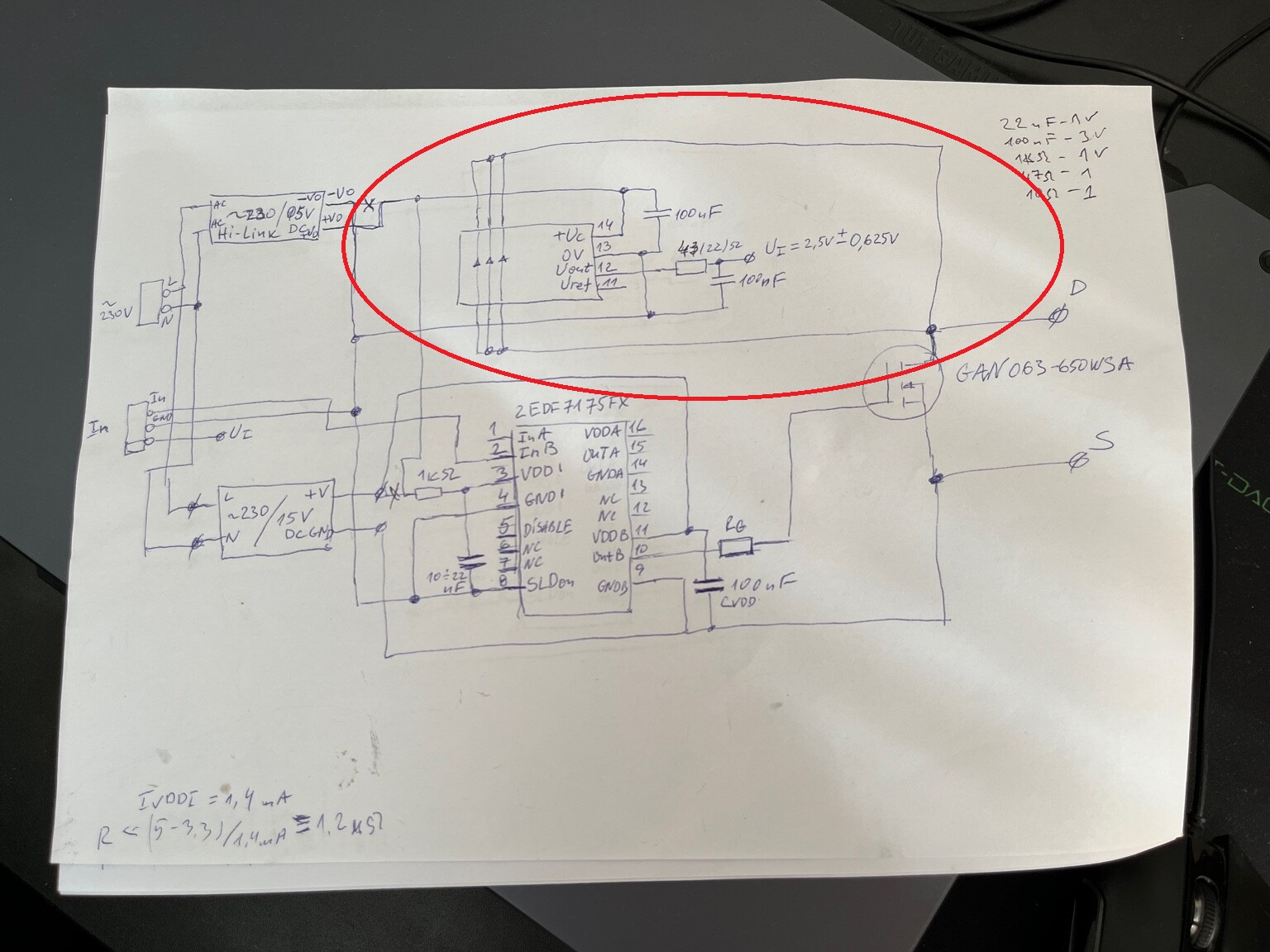
So let's have a look at the hardware first. Can you post a schematic? Also, controlling transistors is probably not the ultimate goal of the setup; what are the transistors in turn switching/driving?

Having said that, I see you're trying to make a PWM output using digitalWrite and millis() timings. This is inefficient and unreliable (due to interrupts). It's a better idea to use counter/timers for this. There are plenty of examples out there; keep in mind that they are platform-specific. For the Arduino UNO, you'd be looking at the ATmega328P timers.

@wafray is using a Due :slight_smile:

And, an UNO, apparently:

Which should work OK for creating a 200kHz waveform - depending on the required PWM resolution of course.

Unfortunately, its not :frowning: or maybe my code is wrong.

Hi,
Thanks for the schematics.

Why have you got the current loop shorted?

Please review your schematic and project?

Can you post some images of your project?
So we can see your component layout.

Thanks.. Tom.. :smiley: :+1: :coffee: :australia:

Hello,

Trust me my project is working fine. I need support for the controling of the transistor with arduino. I have achieved some results, but i need more frequency.

Because you input the frequency in kHz, but calculate the interval as if you have a frequency in Hertz:

 freq_kHz = newFreq_kHz;
 interval = 1000000 / (freq_kHz * 4); 

Using a kHz, you have to multiply your freq value by 1000 to obtain a correct timings.

What part are you not sure about?
Have you started reading the timer chapters in the datasheet of either the ATSAM3X8E or the ATMega328P?

I'd recommend starting with the UNO because this one is better documented in the Arduino community, and there will be more examples available of how to generate block waves with the Timers on the 328P. See e.g. here: arduino uno - I need a 10KHZ PWM signal from pin 3 and 11 using timer 2 - Arduino Stack Exchange

What kind of duty cycle do you need? Especially if a fixed 50% is OK, you can go pretty high up in frequency - essentially to half the core clock speed. If you need a variable duty cycle, the maximum frequency you can output PWM with depends on the resolution you need.

Thank you!

I wii try, thank you. The duty cycle should be 50%

OK, 50% duty cycle is a convenient starting point; makes things a lot easier. Start reading on timers; it's a little technical, but once you get the hang of it, the principles turn out to be not too difficult to wrap your head around. At that point it becomes a matter of setting up a test that outputs a single PWM signal to a single pin, and then working your way upwards in complexity.

Can you check it, now im using " Due timer" library. So maybe will work now?

#include <Wire.h>
#include <LiquidCrystal_I2C.h>
#include <DueTimer.h>

LiquidCrystal_I2C lcd(0x27, 16, 2);

const int potPin = A0;
const int freqPins[] = {9, 10, 11, 7};
int currentPWM = 0;
int freq_kHz = 10;
bool usePot = true;
int dutyCycle = 50;

void setup() {
    Serial.begin(9600);
    lcd.init();
    lcd.backlight();
    delay(1000);

    lcd.setCursor(0, 0);
    lcd.print("Initializing...");
    delay(2000);
    lcd.clear();

    for (int i = 0; i < 4; i++) {
        pinMode(freqPins[i], OUTPUT);
        digitalWrite(freqPins[i], LOW);
    }

    Serial.println("Enter frequency in kHz to set frequency digitally.");
    Serial.println("Enter 'P' to switch to potentiometer input.");
    Serial.println("Enter 'D' followed by duty cycle in percent (0 - 100) to set duty cycle.");

    Timer3.attachInterrupt(pwmCycle).start(1000000 / (freq_kHz * 4));

    updateDisplay();
}

void loop() {
    if (Serial.available() > 0) {
        String input = Serial.readStringUntil('\n');
        input.trim();
        Serial.print("Received input: ");
        Serial.println(input);

        if (input.equalsIgnoreCase("P")) {
            usePot = true;
            Serial.println("Switched to potentiometer input.");
        } else if (input.startsWith("D")) {
            int newDutyCycle = input.substring(1).toInt();
            Serial.print("Converted duty cycle to int: ");
            Serial.println(newDutyCycle);

            if (newDutyCycle >= 0 && newDutyCycle <= 100) {
                dutyCycle = newDutyCycle;
                Serial.print("Duty cycle set to: ");
                Serial.print(dutyCycle);
                Serial.println("%");
                updateDisplay();
            } else {
                Serial.println("Error: Duty cycle out of range (0 - 100%)");
            }
        } else {
            int newFreq_kHz = input.toInt();
            Serial.print("Converted input to int: ");
            Serial.println(newFreq_kHz);

            if (newFreq_kHz >= 1) {
                freq_kHz = newFreq_kHz;
                Timer3.setPeriod(1000000 / (freq_kHz * 4));
                usePot = false;
                Serial.print("Frequency set to: ");
                Serial.print(freq_kHz);
                Serial.println(" kHz");
                updateDisplay();
            } else {
                Serial.println("Error: Frequency must be greater than 0 kHz");
            }
        }
    }

    if (usePot) {
        int potValue = analogRead(potPin);
        int newFreq_kHz = map(potValue, 0, 1023, 1, 1000);

        if (newFreq_kHz != freq_kHz) {
            freq_kHz = newFreq_kHz;
            Timer3.setPeriod(1000000 / (freq_kHz * 4));
            updateDisplay();
        }
    }
}

void pwmCycle() {
    for (int i = 0; i < 4; i++) {
        digitalWrite(freqPins[i], LOW);
    }

    unsigned long pulseWidth = (Timer3.getPeriod() * dutyCycle) / 100;

    digitalWrite(freqPins[currentPWM], HIGH);
    delayMicroseconds(pulseWidth);
    digitalWrite(freqPins[currentPWM], LOW);

    currentPWM = (currentPWM + 1) % 4;
}

void updateDisplay() {
    lcd.clear();
    lcd.setCursor(0, 0);
    lcd.print("Freq: ");
    lcd.print(freq_kHz);
    lcd.print(" kHz   ");
    lcd.setCursor(0, 1);
    lcd.print("Duty: ");
    lcd.print(dutyCycle);
    lcd.print("%   ");
}

Or this?

#include <Wire.h>
#include <LiquidCrystal_I2C.h>
#include <DueTimer.h>

LiquidCrystal_I2C lcd(0x27, 16, 2);

const int potPin = A0;
const int freqPins[] = {9, 10, 11, 7};
int currentPWM = 0;
int freq_kHz = 10;
bool usePot = true;
int dutyCycle = 50;

void setup() {
    Serial.begin(9600);
    lcd.init();
    lcd.backlight();
    delay(1000);

    lcd.setCursor(0, 0);
    lcd.print("Initializing...");
    delay(2000);
    lcd.clear();

    for (int i = 0; i < 4; i++) {
        pinMode(freqPins[i], OUTPUT);
        digitalWrite(freqPins[i], LOW);
    }

    Serial.println("Enter frequency in kHz to set frequency digitally.");
    Serial.println("Enter 'P' to switch to potentiometer input.");
    Serial.println("Enter 'D' followed by duty cycle in percent (0 - 100) to set duty cycle.");

    Timer3.attachInterrupt(pwmCycle).start(1000000 / (freq_kHz * 1000 * 4));

    updateDisplay();
}

void loop() {
    if (Serial.available() > 0) {
        String input = Serial.readStringUntil('\n');
        input.trim();
        Serial.print("Received input: ");
        Serial.println(input);

        if (input.equalsIgnoreCase("P")) {
            usePot = true;
            Serial.println("Switched to potentiometer input.");
        } else if (input.startsWith("D")) {
            int newDutyCycle = input.substring(1).toInt();
            Serial.print("Converted duty cycle to int: ");
            Serial.println(newDutyCycle);

            if (newDutyCycle >= 0 && newDutyCycle <= 100) {
                dutyCycle = newDutyCycle;
                Serial.print("Duty cycle set to: ");
                Serial.print(dutyCycle);
                Serial.println("%");
                updateDisplay();
            } else {
                Serial.println("Error: Duty cycle out of range (0 - 100%)");
            }
        } else {
            int newFreq_kHz = input.toInt();
            Serial.print("Converted input to int: ");
            Serial.println(newFreq_kHz);

            if (newFreq_kHz >= 1) {
                freq_kHz = newFreq_kHz;
                Timer3.setPeriod(1000000 / (freq_kHz * 1000 * 4));
                usePot = false;
                Serial.print("Frequency set to: ");
                Serial.print(freq_kHz);
                Serial.println(" kHz");
                updateDisplay();
            } else {
                Serial.println("Error: Frequency must be greater than 0 kHz");
            }
        }
    }

    if (usePot) {
        int potValue = analogRead(potPin);
        int newFreq_kHz = map(potValue, 0, 1023, 1, 1000);

        if (newFreq_kHz != freq_kHz) {
            freq_kHz = newFreq_kHz;
            Timer3.setPeriod(1000000 / (freq_kHz * 1000 * 4));
            updateDisplay();
        }
    }
}

void pwmCycle() {
    for (int i = 0; i < 4; i++) {
        digitalWrite(freqPins[i], LOW);
    }

    unsigned long pulseWidth = (Timer3.getPeriod() * dutyCycle) / 100;

    digitalWrite(freqPins[currentPWM], HIGH);
    delayMicroseconds(pulseWidth);
    digitalWrite(freqPins[currentPWM], LOW);

    currentPWM = (currentPWM + 1) % 4;
}

void updateDisplay() {
    lcd.clear();
    lcd.setCursor(0, 0);
    lcd.print("Freq: ");
    lcd.print(freq_kHz);
    lcd.print(" kHz   ");
    lcd.setCursor(0, 1);
    lcd.print("Duty: ");
    lcd.print(dutyCycle);
    lcd.print("%   ");
}

Upload it, put a scope on the pin and see!

I have corrected my program with timers but at the moment i have received 25.40 KHZ - but i need 200 khz. Could someone help with that?

#include <Wire.h>
#include <LiquidCrystal_I2C.h>

// Инициализация на LCD дисплея с адрес 0x27 и размер 16x2
LiquidCrystal_I2C lcd(0x27, 16, 2);

const int potPin = A0;
const int freqPins[] = {9, 10, 11, 7}; // Пинове за транзисторите
int currentPWM = 0;
int freq_kHz = 200; // Начална честота в kHz
unsigned long interval = 1000000 / (freq_kHz * 4); // Интервал между импулсите за всеки транзистор в микросекунди
unsigned long previousMicros = 0;
bool usePot = true;
int dutyCycle = 50; // Запълване по подразбиране - 50%

void setup() {
  Serial.begin(9600);
  
  // Инициализация на LCD дисплея
  lcd.init();
  lcd.backlight(); // Включване на подсветката на LCD
  delay(1000); // Кратко закъснение след инициализация

  // Показване на тестово съобщение на LCD дисплея
  lcd.setCursor(0, 0); 
  lcd.print("Initializing...");
  
  delay(2000); 
  lcd.clear();

  for (int i = 0; i < 4; i++) {
    pinMode(freqPins[i], OUTPUT);
    digitalWrite(freqPins[i], LOW);
  }

  Serial.println("Enter frequency in kHz to set frequency digitally.");
  Serial.println("Enter 'P' to switch to potentiometer input.");
  Serial.println("Enter 'D' followed by duty cycle in percent (0 - 100) to set duty cycle.");

  updateDisplay();
}

void loop() {
  if (Serial.available() > 0) {
    String input = Serial.readStringUntil('\n');
    input.trim();
    Serial.print("Received input: ");
    Serial.println(input);

    if (input.equalsIgnoreCase("P")) {
      usePot = true;
      Serial.println("Switched to potentiometer input.");
    } else if (input.startsWith("D")) {
      int newDutyCycle = input.substring(1).toInt();
      Serial.print("Converted duty cycle to int: ");
      Serial.println(newDutyCycle);

      if (newDutyCycle >= 0 && newDutyCycle <= 100) {
        dutyCycle = newDutyCycle;
        Serial.print("Duty cycle set to: ");
        Serial.print(dutyCycle);
        Serial.println("%");
        updateDisplay();
      } else {
        Serial.println("Error: Duty cycle out of range (0 - 100%)");
      }
    } else {
      int newFreq_kHz = input.toInt();
      Serial.print("Converted input to int: ");
      Serial.println(newFreq_kHz);

      if (newFreq_kHz >= 1) {
        freq_kHz = newFreq_kHz;
        interval = 1000000 / (freq_kHz * 4); // Актуализация на интервала за новата честота
        usePot = false;
        Serial.print("Frequency set to: ");
        Serial.print(freq_kHz);
        Serial.println(" kHz");
        updateDisplay();
      } else {
        Serial.println("Error: Frequency must be greater than 0 kHz");
      }
    }
  }

  if (usePot) {
    int potValue = analogRead(potPin);
    int newFreq_kHz = map(potValue, 0, 1023, 50, 200); // Актуализация на честотата според потенциометъра

    if (newFreq_kHz != freq_kHz) {
      freq_kHz = newFreq_kHz;
      interval = 1000000 / (freq_kHz * 4); // Актуализация на интервала за новата честота
      updateDisplay();
    }
  }

  unsigned long currentMicros = micros();

  if (currentMicros - previousMicros >= interval) {
    previousMicros = currentMicros;
    pwmCycle();
  }
}

void pwmCycle() {
  unsigned long pulseWidth = (interval * dutyCycle) / 100;

  digitalWrite(freqPins[currentPWM], HIGH);
  delayMicroseconds(pulseWidth);
  digitalWrite(freqPins[currentPWM], LOW);

  currentPWM = (currentPWM + 1) % 4;
}

void updateDisplay() {
  lcd.clear();
  lcd.setCursor(0, 0);
  lcd.print("Freq: ");
  lcd.print(freq_kHz);
  lcd.print(" kHz   ");
  lcd.setCursor(0, 1);
  lcd.print("Duty: ");
  lcd.print(dutyCycle);
  lcd.print("%   ");
}

Your approach of using micros() to do this kind of timing is a dead-end street. You'll need to use actual Timers to get this to work well, especially if you're going to be working at hundreds of kHz.

For the Arduino UNO etc. (so the plain old ATMega 328P) there's a primer on what the Timers can do w.r.t. PWM here: https://docs.arduino.cc/tutorials/generic/secrets-of-arduino-pwm/
Here's an overview of many of the features including several examples: Timer and PWM - Part 1 (8-Bit Timer0/2) Timer and PWM - Part 1 (8-Bit Timer0/2)%•Wolles Elektronikkiste% % • Wolles Elektronikkiste

The key is that you don't need much resolution; 50% duty cycle is OK, which essentially is 1 bit resolution. This means you can go pretty fast.

For the Arduino DUE the principle will be similar; the registers will be different though since those are controller-specific.
The Arduino UNO is very well documented so my suggestion would be to start with that one so you can rely on the plenty of guides on the use of Timers. Then when you get it to work and understand the principles, see if you can recreate the success on the DUE.

#include <Wire.h>
#include <LiquidCrystal_I2C.h>
#include <DueTimer.h>

// Инициализация на LCD дисплея с адрес 0x27 и размер 16x2
LiquidCrystal_I2C lcd(0x27, 16, 2);

const int potPin = A0;
const int freqPins[] = {9, 10, 11, 7}; // Пинове за транзисторите
int currentPWM = 0;
int freq_kHz = 10; // Начална честота в kHz
int dutyCycle = 50; // Запълване по подразбиране - 50%
bool usePot = true;

void setup() {
  Serial.begin(9600);
  
  // Инициализация на LCD дисплея
  lcd.init();
  lcd.backlight(); // Включване на подсветката на LCD

  // Показване на тестово съобщение на LCD дисплея
  lcd.setCursor(0, 0); 
  lcd.print("Initializing...");
  
  delay(2000); 
  lcd.clear();

  for (int i = 0; i < 4; i++) {
    pinMode(freqPins[i], OUTPUT);
    digitalWrite(freqPins[i], LOW);
  }

  Serial.println("Enter frequency in kHz to set frequency digitally.");
  Serial.println("Enter 'P' to switch to potentiometer input.");
  Serial.println("Enter 'D' followed by duty cycle in percent (0 - 100) to set duty cycle.");

  updateDisplay();
  setupTimer();
}

void loop() {
  if (Serial.available() > 0) {
    String input = Serial.readStringUntil('\n');
    input.trim(); // Премахва излишни интервали и нови редове
    handleSerialInput(input);
  }

  if (usePot) {
    int potValue = analogRead(potPin);
    int newFreq_kHz = map(potValue, 0, 1023, 1, 1000); // Актуализация на честотата според потенциометъра

    if (newFreq_kHz != freq_kHz) {
      freq_kHz = newFreq_kHz;
      updateDisplay();
      setupTimer();
    }
  }
}

void handleSerialInput(String input) {
  Serial.print("Input Received: ");
  Serial.println(input); // Показва въведения вход

  if (input.equalsIgnoreCase("P")) {
    usePot = true;
    Serial.println("Switched to potentiometer input.");
  } else if (input.startsWith("D")) {
    int newDutyCycle = input.substring(1).toInt();
    Serial.print("Parsed Duty Cycle: ");
    Serial.println(newDutyCycle);

    if (newDutyCycle >= 0 && newDutyCycle <= 100) {
      dutyCycle = newDutyCycle;
      Serial.print("Duty cycle set to: ");
      Serial.print(dutyCycle);
      Serial.println("%");
      updateDisplay();
      setupTimer();
    } else {
      Serial.println("Error: Duty cycle out of range (0 - 100%)");
    }
  } else {
    int newFreq_kHz = input.toInt();
    Serial.print("Parsed Frequency: ");
    Serial.println(newFreq_kHz);

    if (newFreq_kHz >= 1) {
      freq_kHz = newFreq_kHz;
      usePot = false;
      Serial.print("Frequency set to: ");
      Serial.print(freq_kHz);
      Serial.println(" kHz");
      updateDisplay();
      setupTimer();
    } else {
      Serial.println("Error: Frequency must be greater than 0 kHz");
    }
  }
}

void setupTimer() {
  // Изчисляване на периода на базата на честотата
  unsigned long period_us = 1000000 / (freq_kHz * 1000); // Преобразуване на kHz в Hz и след това в периода в микросекунди
  
  // Изчисляване на продължителността на импулса на базата на duty cycle
  unsigned long pulseWidth_us = (period_us * dutyCycle) / 100;

  // Настройка на таймера за новата честота и duty cycle
  Timer3.attachInterrupt(pwmCycle).start(period_us);
}

void pwmCycle() {
  digitalWrite(freqPins[currentPWM], HIGH);
  delayMicroseconds((1000000 / (freq_kHz * 1000)) * dutyCycle / 100);
  digitalWrite(freqPins[currentPWM], LOW);

  currentPWM = (currentPWM + 1) % 4;
}

void updateDisplay() {
  lcd.clear();
  lcd.setCursor(0, 0);
  lcd.print("Freq: ");
  lcd.print(freq_kHz);
  lcd.print(" kHz   ");
  lcd.setCursor(0, 1);
  lcd.print("Duty: ");
  lcd.print(dutyCycle);
  lcd.print("%   ");
}


This is my code with real 35 khz and thanks!

Best Regards,

Thanks. As said before, you need to use the Timer registers to get higher frequencies. Using delayMicroseconds() to crate delays won't work. Read the links I posted in #19.

I think your best approach would be to use a Timer in CTC mode.

Section 17.7.2 for Timer2 on the ATMega328P (e.g. Arduino UNO classic, Nano classic).
Frequency is determined as follows:
image
So for 200kHz and a Nano/UNO running at default 16MHz and a prescaler of 8, you would have:
OCRnx = fclk/(fo * 2 * N) + 1 = 16000000/(200000 * 2 * 8) + 1 = 6

So for Timer2 you need to:

  • Set the Timer2 to CTC mode
  • Set one of its associated pins (e.g. D11) to output mode
  • Set the timer prescaler to 8
  • Set the compare register OCR2A to 6

The code should look something like this for Timer2 outputting a 50% duty cycle waveform on Arduino pin 11 (=GPIO PB3):

void setup() {
  TCCR2A = (1<<COM2A0) + (1<<WGM21); // Toggle output on compare match; run in CTC mode
  TCCR2B = (1<<CS21); // prescaler = 8; 
  OCR2A = 6;
  pinMode(11, OUTPUT);  //Set pin as OUTPUT; Arduino UNO pin 11 = GPIO PB3 on the Mega 328P, which is associated with Timer 2
}

void loop() {
  //No code needed to toggle the output pin; the timer runs as a hardware peripheral in the background
}

I've NOT tested the code above, but you could try and run it on an Arduino UNO or Nano, hook up a scope to pin 11 and see what you get.