I'm not familiar with the "/ 4" statement. What is it doing? Looks like a short cut for sure. Not sure though how I would use it . Can you explain. Maybe this is something I should already know.
Dividing by 4
i.e. 1023 / = 255
oops my mistake, sorry 
Just realized you want 180
/ 4 will not give you 180 ![]()
I was thinking about analogWrite() not myservo.write()
Hi, @rfeist11
Can you please post a copy of your circuit, in CAD or a picture of a hand drawn circuit in jpg, png?
Hand drawn and photographed is perfectly acceptable.
Please include ALL hardware, power supplies, component names and pin labels.
Please do not use Fritzy copy and paste.
Thanks.. Tom.. ![]()
![]()
![]()
![]()
Working on the schematic right now in TinkerCad. If I can get a view of it I will post when I have the build complete or I'll just make a hand sketch. It will be a week or so before I receive the poteniometers needed. I was really looking for someone who might be doing a similar build and be able to pick up some tips. I should have waited on this post until it was completed. Thanks for your input.
The important thing about servos is to remember when they start moving they demand a lot of current.
An MG996R for example needs a bit more than 1 amp at start up time.

-
Also, if you want to move multiple servos at the same time you need to make each servo move a small distance then go to the next servo etc.
-
You continue to move the servos a bit at a time until it/they have reached their desired angle.
In this project I'm using sg90 servos. It has been suggested on other forums that a 4 pack of 1.5V batteries will drive all 5 of the servos. Is that correct? Remember I'm just doing this small project to better understand all that is happening. I don't intend to really do anything of any real significance. Just playing around and maybe learn something!
4 X AA batteries should be able to supply 2A surges.
Not sure of the start up current needed to move SG90s ![]()
Remember what is connected to the motor horn will affect the current draw.
Thanks for your input. I'll get the thing together and see how it preforms. I will say as much when I post the full project. Have a good evening. Many Thanks.
1 Like
Update: I would like to first offer thanks to all who offered advise and questions!
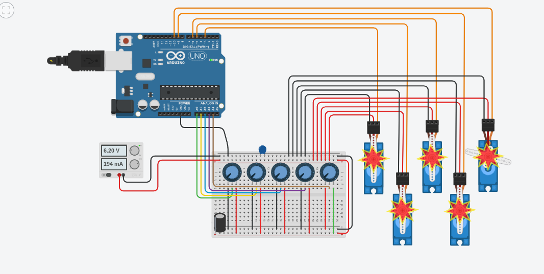
Now as for the project, I received needed potentiometers early and completed the build except for the pincer at the very end. I will attach the wiring diagram that I created with TinkerCad. Please note that the capacitors shown could not be rotated to fit on the breadboard in their respective +/- pins. As for the power supply, I first used 4-1.5V batteries in series. The arm was a twitching crazily and the current only lasted for maybe a hour. I then switched to a Hyelec AC/125 to DC/30V-5A bench power supply. Still not very stable, but I didn't have to worry about buying more batteries.
All in all I would have to say for me this project was a bust! Although I did learn some things above power consumption. But enjoyed it all the same.
In closing, below I have uploaded the Arduino sketch.(which did work!) The wiring diagram and a parts list. Maybe someone will take what I have done thus far and create a better build. Have a great day!
// Controlling 5 servos using 5 potentiometers (variable resistor)
// by Daniel Wright 2010-01-14 (Original)
// Updated by Richard Feist 2023-10-29
// based on the Daniel Wright sketch

#include <Servo.h>

Servo myservo1;  // create servo object to control the first servo
Servo myservo2;  // create servo object to control the second servo
Servo myservo3;  // create servo object to control the third servo
Servo myservo4;  // create servo object to control the forth servo
Servo myservo5;  // create servo object to control the fifth servo

int potpin1 = 0;  // analog pin used to connect the first potentiometer
int val1;    // variable to read the value from the first analog pin
int potpin2 = 1;  // analog pin used to connect the second potentiometer
int val2;    // variable to read the value from the second analog pin
int potpin3 = 2;  // analog pin used to connect the third potentiometer
int val3;    // variable to read the value from the third analog pin
int potpin4 = 3;  // analog pin used to connect the forth potentiometer
int val4;    // variable to read the value from the forth analog pin
int potpin5 = 4;  // analog pin used to connect the fifth potentiometer
int val5;    // variable to read the value from the fifth analog pin

void setup()
{
  myservo1.attach(3);  // attaches the first servo on pin 3 to the servo object
  myservo2.attach(5);  // attaches the second servo on pin 5 to the servo object
  myservo3.attach(6);  // attaches the third servo on pin 6 to the servo object
  myservo4.attach(9);  // attaches the forth servo on pin 9 to the servo object
  myservo4.attach(10);  // attaches the fifth servo on pin 10 to the servo object
}


void loop()
{
  val1 = analogRead(potpin1);            // reads the value of the first potentiometer (value between 0 and 1023)
  val1 = map(val1, 0, 1023, 0, 180);     // scale it to use it with the first servo (value between 0 and 180)
  myservo1.write(val1);                  // sets the first servos position according to the scaled value
  delay(15);                           // waits for the first servo to get there
//
  val2 = analogRead(potpin2);            // reads the value of the second potentiometer (value between 0 and 1023)
  val2 = map(val2, 0, 1023, 0, 180);     // scale it to use it with the second servo (value between 0 and 180)
  myservo2.write(val2);                  // sets the second servos position according to the scaled value
  delay(15);                           // waits for the second servo to get there
//
  val3 = analogRead(potpin3);            // reads the value of the third potentiometer (value between 0 and 1023)
  val3 = map(val3, 0, 1023, 0, 180);     // scale it to use it with the third servo (value between 0 and 180)
  myservo3.write(val3);                  // sets the third servos position according to the scaled value
  delay(15);                           // waits for the second servo to get there
//
  val4 = analogRead(potpin4);            // reads the value of the forth potentiometer (value between 0 and 1023)
  val4 = map(val4, 0, 1023, 0, 180);     // scale it to use it with the forth servo (value between 0 and 180)
  myservo4.write(val4);                  // sets the forth servos position according to the scaled value
  delay(15);                           // waits for the second servo to get there
//
  val5 = analogRead(potpin5);            // reads the value of the fifth potentiometer (value between 0 and 1023)
  val5 = map(val5, 0, 1023, 0, 180);     // scale it to use it with the fifth servo (value between 0 and 180)
  myservo5.write(val5);                  // sets the fifth servos position according to the scaled value
  delay(15);                           // waits for the second servo to get there

}
Parts List:
1 - Arduino Uno R3
1 - Hyelec 125V AC - 30V-5A DC bench power supply
5 - 10K Potentiometers
5 - SG90 9g (Cheap) Servo motors
1 - Electrolytic 10uF Capacitor
1 - Ceramic 1000nF Capacitor
I would offer a pic of the build, but still kind of embarrassed by it all. Just imagine servo mounted by the horn to a 10" by 10" piece of MDF. Then a servo (with a 7" tongue depressor mounted to the base of that servo) mounted to the side of the first servo by the horn . Followed by a "second arm" with 3 additional servos.
Hope some one finds this project interesting. And I hope I have stayed within community guidelines with this post. By the way this post is intended for viewing. I'm not asking any questions. But look forward to any comments or thoughts anyone might have.
Hope you had your power supply current limiting set sufficiently high.
The servos take the current that they need, current limiting set too low will cause problems.
Hint
When experimenting with your Arduino, suggest you place a 220R resistor in series with both inputs and outputs as it can save your Arduino pins from miswiring problems. ![]()
Your potentiometers should be powered from the Arduino 5v power supply !
![]()
Just tried moving power from Arduino to pots! Thanks much. All twitching is pretty well gone. I'll keep on messing with the project.
Maybe move a servo when there is a difference of “X” from last reading to this reading.
Also try reading the potentiometers once per 100ms (or whatever).
Update: Conclusion. I completed this project only to come to the harsh reality that the combination of very weak SG90 servo motors and the weight of the "tongue depressor" frame, the motors stalled out too often to make this an enjoyable project. I do admit that I read in several articles that warned that this class of servo would not work very well, but I still persisted.
In closing, I would like to thank all who offered comments and solutions. It was all very helpful. In the future I will not post anything in the manner this posting started out! Everyone have a nice day!
Hello to all, This is an update on my newest robotic arm project. I read online about a build that was offered by Ashing. Here is a link to a, Play and Record, sketch where the author claims that the build is connected to Arduino Nano only. No external power supply?
Link: Record and Play 3D Printed Robotic Arm using Arduino.
At near the beginning they layout the necessary components. 5 MG995 servos, 5 potentiometers.
Well, here is my take thus far.(By the way I'm not bashing their work. It's just things are not panning out!). With that said, I purchased a Ender Pro 3. Downloaded all of the stl. files from Ashings web site. I then proceeded to print out the parts using Cura for slicing to create g-code. In the article link posted above it is said that the print time was approximately 4 1/2 hours. For the Ender Pro it was a little over 23 1/2 hours.
Next, in the article there is a schematic and a picture of 5 pot's, a Arduino Nano, 5 doubled sets of pins and a barrel jack. Which the jack is suggested as an option. In the paragraph above it reads about the power consumption when one servo is in motion. What I found out was when I had the power supply set to 6.5V @ .15 amp my MG955 would not even respond. The value of amps had to be at least 1.5 amps for it to do a simple sweep of 0 to 170 and back. I then connected a horn and one of the parts from the arm that has a couple of holes at the other end and connected a writing pen with string. Edited the sketch to move from 0 to 45 then back. I had to adjust the amps to 1.8 for a clean motion. I then connected one of the MG955. Had to adjust to 2.5 amps.
In conclusion, I have become very skeptical about what is available online in the way of education. It's more like listening to someone on the radio rant about a subject. Take it at face value.
As for my project, I am taking a slow approach this time. I started with the structure of the arm and the various components. I have since learned from online tutorials on FreeCAD and I'm in the process of editing nearly all of parts. This is mainly for securing the servos with machine screws and nuts versus screws. At this time I only have a 30v 5amp bench power supply. Before I upgrade to a greater level of supply I will be testing as each servo is added to see how the servos react as greater stress is applied and what that means for power requirements. If anyone would care to offer their comments, please do so. Again this post is meant for discussion not a challenge to anyone else who has been successful in these types of projects. I do however have a question for anyone that has actually completed this project successfully. What is used to power a 5 MG955 robotic arm? Thanks again.
Hi, @rfeist11
Looks like you are on top of analysing the situation, good work.
The Arduino is powered through the USB port and the +5v pin on the board is used to power the potentiometer and the Servo motors. In our Robotic Arm at any given instance of time only one servo motor will be in motion hence the current consumed will be less than 150mA which can be sourced by the on-board voltage regulator of the Arduino Board.
Would definitely ring warning bells as the bottom servo must be having to supply some torque to support the rest. of the arm, or any load.

There looks like a lot of effort has gone into the programming of the sketch but not into the actual performance.
I like your next step, test out each individual servo in its position and get usable data. ![]()
Tom... ![]()
![]()
![]()
![]()
This topic was automatically closed 180 days after the last reply. New replies are no longer allowed.