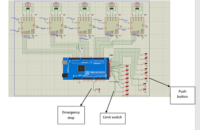
im controlling 5 stepper motors using arduino mega .two of them have to be synchronized( like moving at the same time and same direction) im using momentary push button for the control,each motor will two momentary push button 1 for backward motion and the other forward motion.i have done the simulation in proteus and it was working well as expected after that i realize that i should include limit switch and emergency stop button in my circuit and integrate it in the code and thats where the problem come up.with those component added in the circuit and the code the motor start moving and stop right away.
i have shared below the code and the circuit.
Thanks in advance!
saisissez ou collez du code ici
```#include <AccelStepper.h>

// Define the pins for the motors
#define motorInterfaceType 1
AccelStepper stepper1(motorInterfaceType, 2, 3, 4, 5);  // Motor 1
AccelStepper stepper2(motorInterfaceType, 6, 7, 8, 9);  // Motor 2 (synchronized with Motor 3)
AccelStepper stepper3(motorInterfaceType, 10, 11, 12, 13);  // Motor 3 (synchronized with Motor 2)
AccelStepper stepper4(motorInterfaceType, 14, 15, 16, 17);  // Motor 4
AccelStepper stepper5(motorInterfaceType, 18, 19, 20, 21); // Motor 5

// Define the pins for the buttons
const int buttons[10] = {22, 23, 24, 25, 27, 29, 31, 33}; // Pins for the buttons

// Define the pins for the limit switches
const int limitSwitches[10] = {34, 35, 36, 37, 38, 39, 40, 41}; // Pins for the limit switches

// Define the pin for the emergency stop button
const int emergencyStopButton = 42; // Pin for the emergency stop button

void setup() {
  Serial.begin(9600);
  for (int i = 0; i < 10; i++) {
    pinMode(buttons[i], INPUT_PULLUP); // Configure the button pins as input with pull-up resistors
    pinMode(limitSwitches[i], INPUT_PULLUP); // Configure the limit switch pins as input with pull-up resistors
  }
  pinMode(emergencyStopButton, INPUT_PULLUP); // Configure the emergency stop button pin as input with pull-up resistor

  // Configure the motors with initial speeds and accelerations
  stepper1.setMaxSpeed(1000);
  stepper1.setAcceleration(500);
  stepper2.setMaxSpeed(1000);
  stepper2.setAcceleration(500);
  stepper3.setMaxSpeed(1000);
  stepper3.setAcceleration(500);
  stepper4.setMaxSpeed(1000);
  stepper4.setAcceleration(500);
  stepper5.setMaxSpeed(1000);
  stepper5.setAcceleration(500);
}

void loop() {
  // Check the buttons and move the motors accordingly
  checkAndMove(stepper1, buttons[0], buttons[1], limitSwitches[0], limitSwitches[1]);
  checkAndMoveSync(stepper2, stepper3, buttons[2], buttons[3], limitSwitches[2], limitSwitches[3]);
  checkAndMove(stepper4, buttons[4], buttons[5], limitSwitches[4], limitSwitches[5]);
  checkAndMove(stepper5, buttons[6], buttons[7], limitSwitches[6], limitSwitches[7]);

  // Check the emergency stop button
  if (digitalRead(emergencyStopButton) == LOW) {
    // Stop all motors
    stepper1.stop();
    stepper2.stop();
    stepper3.stop();
    stepper4.stop();
    stepper5.stop();
  }

  // Run the motors
  stepper1.run();
  stepper2.run();
  stepper3.run();
  stepper4.run();
  stepper5.run();
}

void checkAndMove(AccelStepper &stepper, int forwardPin, int backwardPin, int limitSwitchForward, int limitSwitchBackward) {
  if (digitalRead(forwardPin) == LOW && digitalRead(limitSwitchForward) == HIGH) {
    stepper.move(200); // Move 200 steps forward
  }
  if (digitalRead(backwardPin) == LOW && digitalRead(limitSwitchBackward) == HIGH) {
    stepper.move(-200); // Move 200 steps backward
  }
}

void checkAndMoveSync(AccelStepper &stepperA, AccelStepper &stepperB, int forwardPin, int backwardPin, int limitSwitchForward, int limitSwitchBackward) {
  if (digitalRead(forwardPin) == LOW && digitalRead(limitSwitchForward) == HIGH) {
    stepperA.move(200); // Move 200 steps forward
    stepperB.move(200); // Move 200 steps forward
  }
  if (digitalRead(backwardPin) == LOW && digitalRead(limitSwitchBackward) == HIGH) {
    stepperA.move(-200); // Move 200 steps backward
    stepperB.move(-200); // Move 200 steps backward
  }
}In your code you define emergency stop as 42.
" const int emergencyStopButton = 42; // Pin for the emergency stop button"
But in your schematic it is wired to A10.
A10 is digital pin 64.
//Analog to Digtal equiv.
//A0 (54) A1(55) A2(56) A3(57) A4(58) A5(59) A6(60) A7(61)
//A8 (62) A9(63) A10(64) A11(65) A12(66) A13(67) A14(68) A15(69)
#define motorInterfaceType 1
AccelStepper stepper1(motorInterfaceType, 2, 3, 4, 5);  // Motor 1
That doesn't fit together. InterfaceType 1 means step/dir driver and needs only 2 pins. Please tell what stepper and driver you are using.
A picture of your setup would help to understand what you are doing and how the limit switches are used.
Can you explain a little bit more? How long does it move?
Like it moves just for 5 second and its very slow
No it is not wired to A10 if you could zoom you will see that its not ...
Im using motor-bitepper and L298 stepper motor driver
I'm not used to this schematic "quality".
I'm from the time when schematic was schematic,
Sorry what do you mean by:
"I'm from the time when schematic was schematic"
??? Can you post a link?
Which link do you want me to post
This topic was automatically closed 180 days after the last reply. New replies are no longer allowed.

