Is there any particular reason you're using that mosfet? There are far better, more modern devices. While the 2N6659 can be directly driven from 5v logic (read the datasheet!), the bigger question remains: what are you trying to drive and at what frequency?
avr_fred:
Is there any particular reason you're using that mosfet? There are far better, more modern devices. While the 2N6659 can be directly driven from 5v logic (read the datasheet!), the bigger question remains: what are you trying to drive and at what frequency?
Very low frequency - it is for an irrigation controller.
What device would you suggest other than FETs or transistors?
Of the devices referenced above, you'll find these devices:
FDP7030BL/FDB7030BL
IRL3705N
IRLZ44N
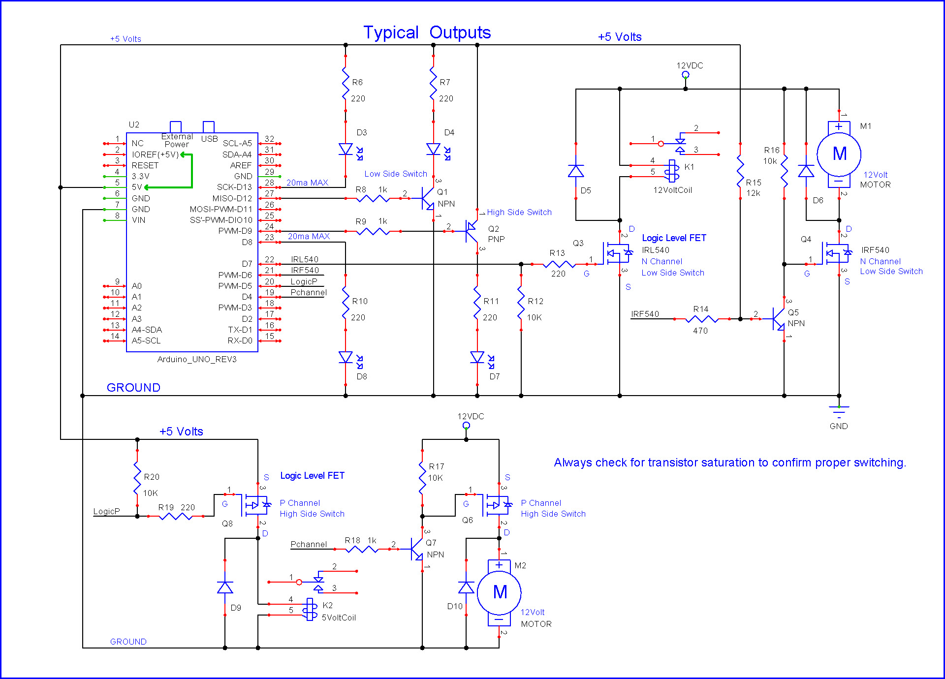
Are in easy to handle TO-220 packages and are suitable for direct drive from an Arduino with the first circuit shown in this link:
Be aware that the fet you use should be "logic level" so that the device is fully turned on with only 4 to 5 volts on the gate. The three devices above meet this requirement. Refer to Nick Gammon's web page mentioned above for more details.
I like his video's, but this one didn't tell the WHOLE story on Vgsth. Just because a fet has a Vgsth of 4.5V, which is <5V doesn't mean it will work with 5V logic levels.
Hi,
Is there a reason for high side switching?
I assume R1 is your load?
Any reason you aren't using an opto-coupler to overcome all the level switching.
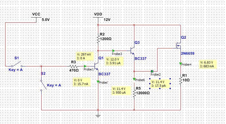
The circuit you have posted will never switch fully ON.
When Q3 turns on and Vg is for an instant higher in potential then Vsource, you will get next to no resistance drain to source.
This means the source will now be almost at Vdd, so the gate potential which is being switched to Vdd by Q3, will be lower than the source voltage, due to Q3 Vcesat.
To make the N-CH MOSFET conduct Vg has to be higher in potential than Vsource.
boylesg:
I am trying to control a solenoid valve that operates at 12V and about 200-300mA
A 150 ohm base resistor, 1N4148 free-wheel diode and 2N2222 or similar high current switching
BJT will be the cheapest method to do that. The diode is essential in any such circuit.
MarkT:
A 150 ohm base resistor, 1N4148 free-wheel diode and 2N2222 or similar high current switching
BJT will be the cheapest method to do that. The diode is essential in any such circuit.
I found some cheap IRLZ44N on ebay.....so I will see how I go with them.
Can some one explain to me the differences between high side and low side switching with FETs - have never really understood it.
High side switching is on the high side, low side switching is on the low side, that's it. You can do it
with a switch or a relay or a semiconductor device.
However you have to realize that switching with a MOSFET is done with a common-source configuration
(or a common-emitter circuit for a BJT), and couple that with the kind of switching and it will be obvious, since the
source terminal is power in, drain is power out. For high-side source is positive supply in, so the device
has to be p-channel.
High side switching allows a common ground - often this is required by the rest of the device.
Low side switching leaves part of the circuit at supply potential, so it has to be isolated from ground,
which is sometimes inconvenient (if it has signals to other parts of your circuit).
For a dumb load though, low-side switching is simpler and you don't have to level shift - its often
used for leds, motors, heaters, etc.
High side switching is usually used for controlling a sensor/peripheral or another whole circuit, where sharing
a common ground is assumed and simplest.
For high voltage loads high-side switching is much safer, and would be recommended.
For loads on the end of a long cable high-side switching is recommended as the cable is also switched off
when the load is.
OK so when you say common ground you are only really referring to the FET and the transistor in the first example.....nothing to do with the rest of the circuit?
So what is likely to happen if you were to invert the positions of the motor and fet n the first example?