For my project, I need a solenoid that I will control with an Arduino. The solenoid will be mounted on the gripper of a UR5e arm. It will be energized for approximately 1s or 2s and then stop for 5s to cool down, leading probably to a duty cycle of around 20-10%.
The system will likely run continuously for 24 hours, so it needs to be as safe and robust as possible.
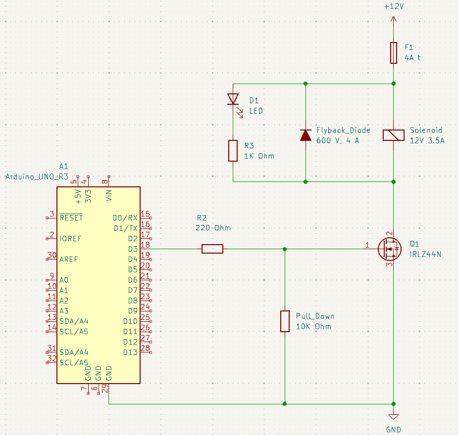
I’ve already prepared an electrical plan for this, but I’m not sure if it’s robust enough. Should I add any additional safety measures?
MOSFET: IRLZ44N (Logic-Level N-Channel MOSFET): UDS: 55 V - Id: 47 A - RDS(on): 22 mOhm - Ptot: 110 W
Flyback Diode:: MUR460 600V, 4A
Fuse: SMD 2410 slow-blow 4A - 125V DC - (100A)
Questions:
If I energize the solenoid for 1 second and stop for 15 seconds, that results in a duty cycle of 1/16 = 6.25%. Would the solenoid draw more than the 42W (42W/12V=3.5A) specified in the datasheet? If so, would this be a problem?
Is the gate resistor placed correctly?
I plan to solder everything on a soldering board. Would using a breakout MOSFET module be advisable here, or is it unnecessary since I’m already using a flyback diode, fuse, and pull-down resistor?
Is a capacitor necessary here, considering the power supply should provide 12V at 5A, which matches the solenoid’s maximum specifications?
Below is the circuit diagram for reference:
The diode is used as a visual feedback.
The resistance of the solenoid is 34Ω.
When powered from a 12V supply, the current will be 12V / 34Ω = 0.353A
The table is saying that if you are using the solenoid at 10% duty cycle, then the power can be 42W (so that the average power is 4.2W).
The voltage needs be raised up to 38V to achieve that power.
At 38V, current = 38V / 34Ω = 1.118A
That power of 42W is obtained from 38V x 1.118A, and not 12V x 3.5A as you suggested.