Ive been working on an energy efficient motion detector with an HC-SR501 motion sensor and an arduino pro mini 3.3v, where the sensor should technically be able to interrupt a sleeping arduino. Only I cant get it to work.
To start, heres my code;
#include <avr/sleep.h>

const int INTERRUPT =  2;        // Pin to wake it up.
const int LED_PIN   =  9;        // LED pin.

void setup()
{
  Serial.begin(9600);           // For debug purposes.
  pinMode(INTERRUPT, INPUT_PULLUP);
  pinMode(LED_PIN, OUTPUT);
  digitalWrite(LED_PIN,HIGH);
}

void loop()
{
  delay(1000);
  Sleep();
}

void Sleep(){
  Serial.println("Going to sleep..");
  sleep_enable();
  attachInterrupt(0,wakeUp,LOW);
  set_sleep_mode(SLEEP_MODE_PWR_DOWN);
  digitalWrite(LED_PIN,LOW);
  delay(1000);
  sleep_cpu();
  Serial.println("I woke up!");
  digitalWrite(LED_PIN,HIGH);
  delay(2000);
}

void wakeUp(){
  Serial.println("Interrupt fired.");
  sleep_disable();
  detachInterrupt(0);
}
With this setup, whenever I touch D2 with GND, the arduino springs back to life. But when I put the sensor signal pin on D2 (HIGH when motion detected), it does nothing. I tried setting INPUT instead of INPUT_PULLUP thinking the signal might be backwards, but that didn't help. I tested the readout from both just touching it to GND and by giving it 3.3v, digitalRead(INTERRUPT) just gives me HIGH in both cases. So it should work.. ?
I know im on the right track but something is wrong, I just cant put my finger on it. Can someone please tell me what it is that I should be doing different?
Yeah I've made sure the sensor is functional. I have bypassed the volt regulator on the sensor so it can run on 3.3v from the pro mini VCC. GND is connected to pro mini GND, and signal is directly connected to pro mini D2. With a volt meter I get a nice 3.3v when the sensor is detecting motion. Serial.println(digitalRead(INTERRUPT)); shows 1 when the sensor sees motion and 0 when it does not. So I believe im getting the correct HIGH/LOW from it. I suspect there is a problem with attaching the interrupt.
attachInterrupt(0,wakeUp,LOW);
I believe this will run wakeUp when it detects LOW on INT0. I have tried setting this to HIGH but it made no difference.
The sensor gives HIGH when triggered and LOW normally. But your Arduino needs LOW to trigger wakeup. So you should invert the sensor's output that when it goes high, then it will get inverted to low. So your Arduino will wakeup. post #3 is right.
@JCA34F It has something to do with INPUT_PULLUP. I've put that in so I could slap a button on it, to test the code. I remove pinMode for D2 when I have the sensor connected, but it doesnt work.
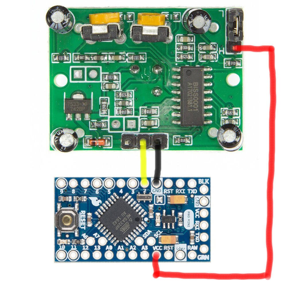
@aarg Three wires shouldnt be too difficult, but here you go.
Feeding 3.3v through the jumper instead of the standard 5v header allows you to bypass the onboard 3v regulator. The sensor functions properly this way, it gives a reliable HIGH/LOW when in normal use (not trying to trigger interrupt).
@ArnavPawarAA Cant I just attach the interrupt with HIGH instead of having to make hardware chances? I've tried but that also did not work for some reason.