Hello! I'm trying to control an LM2596 based Buck Converter with an arduino without any success.
Here is the setup:
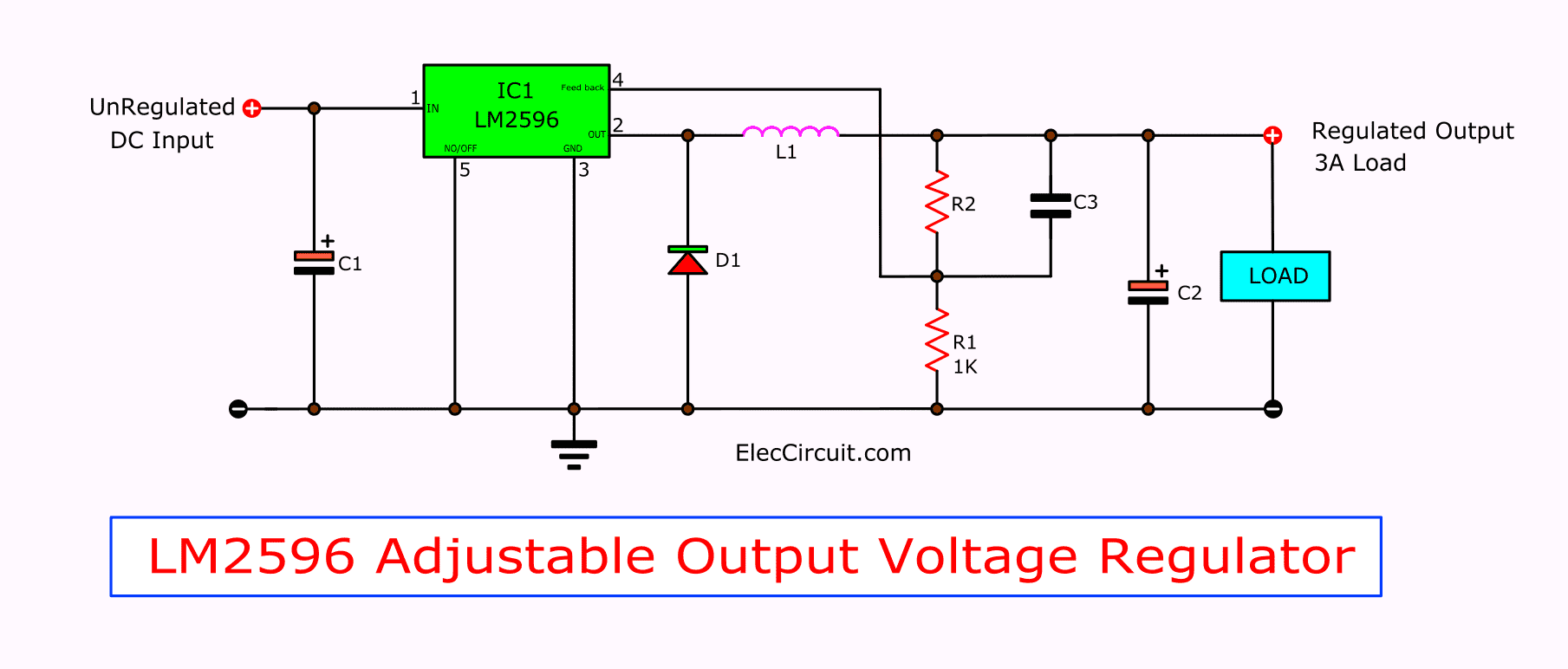
I removed the trim-pot from the converter board, connected a 1K resistor from the feedback pin to a buffered RC filter and with a voltage divider ran the output of the converter to an Analog input. I also added a 10uF cap at the power rails for stability. The load is just a regular blue LED.
Before adding the "255-output" line, I had no signal from the PWM pin, but after doing so, I have a ~50% duty cycle signal which doesn't change at all (even if I disconnect the load or add a new one).
I only changed the setpoint value (previously it was reading an analog value from a pot), added the Serial.print lines and cleaned it up a bit. Here is the original tutorial.
Later I also tried adding the trim pot, but I still can't control voltage with the microcontroller.
Is this method going to work out in the end or should I try to come up with something else?
This was going to be a part of my big project, so I can't really do anything else before I solve this.
I would love to hear your suggestions!
This would be an extremely dodgy way to control a voltage regulator; if the code crashes it would either turn the regulator fully on or completely off. Not a good idea!
And it is indeed complete nonsense, since the potentiometer in this case for the LM2596 is not setting a constant voltage, but is part of the feedback loop which is supposed to control the regulator.
All delays are based on a clock, maybe millis(). Beginners should understand the BlinkWithoutDelay example for repetitions and try to extend it for single shot action.
And as UwePaul pointed out the use of PWM is nonsense in this project. A digital pot under control of the Arduino may be usable, but only for setting the desired output voltage without any PID regulation.
It's not matter of what you can, but of what you need. No regulator is needed hence no PID. Set the digital pot once to the proper value and you are done.
Why would you want to control an LM2596 based Buck Converter with an Arduino anyway? It does not look practical, so let's see what the real problem is.
I want to make a decent bench supply. I wanted it to be not very big in volume, to have more than one isolated channel and some other stuff.
To reduce the volume, I decided to make it more efficient than just a regular linear regulator. The plan is to lower the voltage coming from the transformer and first running it through a switch mode converter and then through the linear one; this way, the linear regulator doesn't waste as much power and doesn't need a gigantic heatsink.
I also considered not using the linear regulator, but I think that it needs too much capacitance at the output and it causes the supply to have a big delay when changing the voltage. Also, I couldn't find any parts locally that could allow me to do that.
I sorted out most things and am now ready to start prototyping.
Thank you guys for recommending me to use a digital pot. I didn't even know it existed.