Hi Guys (First ever post, sorry if I messed anything up here)
I would really appreciate any help as I've almost given up and thrown away hundreds of euros I've tried everything to get the Adduino + CAN-BUS Shield + RMD-X6 to work.
I can control the motor using the USB UART and the MyActuator software.
What I've tried so far ..
Added 2, 120 Ohm Resistors on each end of the cable.
Tried removing one as I read there is a built in one on the motor side.
I changed CAN_1000KBPS to CAN_500KBPS,
I tried every ID (7,8,9,10,11,...).
I got two shields, a Sparkfun Electronics CAN-BUS Shield and a Seeed Studio Shield.
I tried using the newer mcp_can.h library and older one.
I must have tried several examples.
I bought two of these motors, the RMD-X6 1:6 And the RMD-X6 S2 1:35.
I wrote several emails to MyActuator but no response.
The below code initiates fine but prints out "error" at the end of the code. I guess
CAN_MSGAVAIL is never equal to CAN.checkReceive().
I hoping obi wan kenobi isn't my only hope, can you help ?
Hi Railroader.
I hope this helps, I tried without any resistors, then one resistor at the shield end, then 2 at each end. The YouTuber Skyentific made it all look so easy.
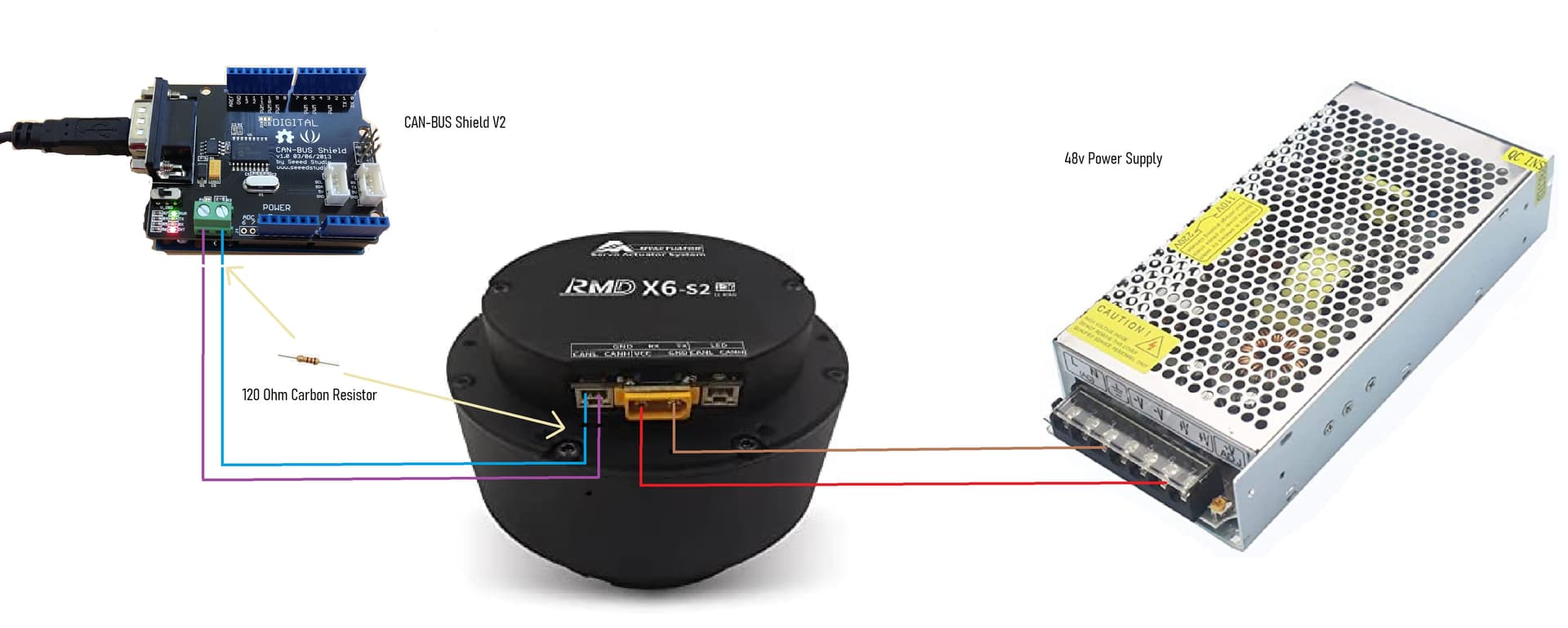
Good block diagram.
Please bring up pen and paper, and show in schematics. Words like "resistor at the end" are not precise enough. No helper is standing behind Your back seing what You see.
Hi Railroader.
The motor comes with a UART to USB cable, and some proprietary software, it works, I can turn the motor, but I'm building a robotic arm, It has 3 other motors (which all work) and 2 of these motors from MyActuator, I'm just not sure how I would integrate my Arduino project and their proprietary software if this was the only way I could control them. I just can't figure out how he ( Skyentific) got them to work, they sell these motors on the https://www.robotshop.com/ website, I can't find anything about these. Was I the only idiot to buy these.
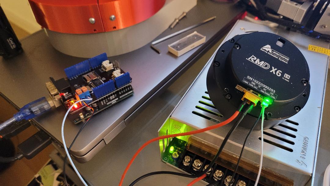
Here's yet another bad diagram, sorry I also need to work on my schematics.
Okey. That explains the resistors. Once worked a lot with CAN bus communication but don't remember those hardware details. Are You sure You should use 120 in two places and not only in one?
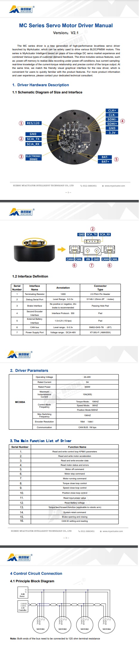
The last line of the documentation suggests this, although I don't get half of what I'm reading to be honest, I should have stuck with something simple and not CAN-BUS as my first project, God they looked so promising in the video.
Wish I could get to the video that was suggested in this post, the video appears to be deleted.
This is the only other post I could find on this motor (Well I got the x6, this person had an x8). I have tried the older and newer libraries but
with no luck.
That's not always good. There are plenty of videos and tutorials made by more or less ignorant people. The best is to get hold of CAN bus definitions, standards, facts....
Check the boards You use. That is quite high speed that possibly is not supported by Your hardware. My guess.....
What CAN commands are supported by the motor? Could You make a special test code just to get some communication/contact running?
That must be a variable. Else it would be accessed by CAN_MSGAVAIL(). The compiler would issue an error if it's wrong. What do You look for in that statement? Good coding implies adding comments to tell the purpose of the statements.
What version driver/CAN protocol are you using? In 3.5 0xA6 is not a command. I wrote driver support for OpenFFBoard for my X8-Pro actuators before discovering I had a old CAN protocol, and just got my rewrite finished.
Confirm that it is not using the V3 driver and the 3.5 protocol, as mine that I've had for a few months now shipped with
Hi 1plus2
First, thank you for helping, I bought them from RobotShop, now I see they have a newer version "MC-X-300-O" it even has a V3 printed on the back, but the one I bought is the "MC300A" (typical me) which must be the older one. Do you know what protocol I have ?, I've wrote to them twice but got nothing back.
Motor 1. RDM-x6 1:6 (SN:10222000203) (MC300A) I'm thinking its the older one
Motor 2. RMD-x6-S2 1:36 (SN:10222000403) I'm also thinking this is an older model as I see a newer one with V2 written on the back
Sorry for the late response, I am probably of no help anymore since I upgraded my firmware to the one included when the supplier sent me the new configuration software and now my CANBus no longer communicates either. No response from MyActuator since then to get a copy of the old firmware and maybe fix these. Because of this I am switching away from their driver for my project.
So my take away seems to be you have the right protocol, but the drivers are no longer transmitting.
Sucks to have almost $800 in bricks. Moteus and ODrive seem to be the current options, but one is out of stock, the other is closed and double the price. This is turning out to be a mess! Let me know if you want to talk about solutions or if MyActuator reaches out with one, for all I know its a setting in the config software I am missing
Thanks so much 1plus2, I may give up and throw them in a river, or maybe I'll hold onto them and jump in the river, my wife is gonna kill me anyway when she finds out they don't work. MyActuator were no help, one guy told me I had the V3 motors, then another told me I had the V2 motors. I'm lost. I had already printed the Robotic Arm and it looked great, now I have to find new motors and reprint.
Hi 1plus2.
Well I have confirmed that the CAN-BUS communication is working, I got a second CAN-BUS shield and Arduino board and was able to send and receive with no issues, this to me confirms the RMD is not working, I tried very command with both the motors, nothing. I'm now reading about the ODrive, thank you. I'll continue to post here anything I can.
Hi there… i have same motors as yours ,the problem is that motor seems not working with single turn mode(A6), try to use A8 it should work i sent an email to the company about this issue