I'm starting to design a project to build a telescope automation system (with an altazimutal mount, which is why the system needs to be computerized) using Arduino.
It means I will have to use electric motors to move the telescope to compensate Earth rotation, and being quite a newbie in electronics (I come from a programming background), I have trouble determining the kind of motor to use.
I originally planned on using brushless DC motors with an ESC but I'm quite confused about how to drive them. Do they require a PID controller? In this case, someone told me the input variable for the PID controller would be the actual and desired angles (in vertical coordinates in my case) of the telescope. If I do this in an infinite loop that continuously recomputes the angles and give them to the PID, will sending the output values of the PID to the ESC be sufficient to have it I-don't-know-how giving the motors the correct speed?
I then saw other similar projects (but using way older and thus way more complex hardware) that used stepper motors or servo motors. However, if I understood correctly, those motors are controlled with an angle command. In this case, will they just try to respond to the command as fast as possible or is it possible to control the speed to ensure the smoothest possible movement?
In any case, what do you think is the best option in terms of motors for such a project... ? Since I plan to do a goto system too (asking the telescope to be at given coordinates), and the telescope itself is quite heavy, it will probably require a bit of torque too...
The stepper motor is not much different from the brushless motor. In this application either one could be used but a stepper will be easier to program and easier to set up mechanically (less gearing required.)
A hobby servo is not appropriate for this although you could look at it like you're building a really big servo.
What are you going to use for position feedback? How does the Arduino know where the telescope mount is pointing when it is switched on? (Not where it's pointing at the sky, just what is the angle on the two axes.)
A potential disadvantage of a stepper motor is the possibility of the steps causing rough motion.
The great advantage is that it is easy to command them to move an exact distance.
With a brushless or DC motor you will need some external device such as a rotary encoder to provide position feedback and that and the PID code will make the program much more complex.
I suspect a hobby servo would not give the position accuracy that you require and a continuous rotation hobby servo will need an external position sensor just like a DC motor. It does have the advantage of self-contained electronics.
Apart from the hobby servos all motors will need a suitable motor driver between the Arduino and the motor.
A PID loop is not very complex really, but expect tinkering to be necessary.
hobby servo does < 180 degrees rotation so inappropriate. A "continuous rotation servo" is nothing
but a small motor with its own driver that accepts PWM control. Generally their build quality is inadequate
for any precision task.
Stepper vibration may be an issue - microstepping will reduce this a lot, note, which means bipolar
chopper driver, not unipolar.
With a quality PMDC or BLDC motor the running will be very smooth, your gearing will be dominant.
Such a motor will need turning into a servomotor (in the true sense, nothing to do with hobby
servo-mechanisms), which means rotary encoder and PID loop
Mechanical backlash will be an issue to address but the telescope mount may already provide
anti-backlash geartrain? You need to know you torque and speed requiments at the motor
shaft before deciding anything though.
Thanks all for your replies! I will try to answer all your questions:
What are you going to use for position feedback? How does the Arduino know where the telescope mount is pointing when it is switched on? (Not where it's pointing at the sky, just what is the angle on the two axes.)
I was planning on using angular position sensors if I used brushless motors but I suspect your question is about the initial position, which I will have to get even with steppers. The easier option is probably just to ask the user to aim at a known position (for example Polaris). Otherwise, I thought about using gyroscopes and magnetoscopes to make this automatic but I don't know if the measure is accurate enough.
Apart from the hobby servos all motors will need a suitable motor driver between the Arduino and the motor.
What do you mean by a motor driver? Something like an ESC?
Mechanical backlash will be an issue to address but the telescope mount may already provide
anti-backlash geartrain? You need to know you torque and speed requiments at the motor
shaft before deciding anything though.
I don't know... the mount already provides a 1:120 reduction gear, it's all I know.
Determining the torque and speed is another of my main issues. I have no idea about how to do. Is measuring the weight of the telescope itself (i.e. without the mount) sufficient if I know the reduction gear ratio? Or maybe there is internal friction to take into account too...
Anyway the maximum speed required will be in "goto" mode where the telescope must change position as fast as possible to a given angular position. In this mode, the exact speed isn't important as long as it's fast so I can probably just take a large estimation ...
So if I understand correctly, the best option would be stepper motors? I saw people using open-loop steppers. Don't you think some form of closed-loop will be necessary in case of external errors at some point?
Thank you very much for help so far, I didn't expect so many replies so quickly.
Leo_:
What do you mean by a motor driver? Something like an ESC?
An ESC is a possibility. AFAIK an ESC appears to the Arduino like a servo.
There are also h-bridge motor drivers that may offer finer control by the Arduino. You will find examples on (say) the Pololu website and many other places.
A motor driver is a circuit that drives a motor. It converts logic signals to high current and power
waveforms necessary for motors. Depends on the type of motor and max current requirements.
Start with the mechanics of the situation. Torque can be measured in various ways, and its the
first thing you need to know. What kind of coupling or shaft is available to drive the mount?
The reduction gearing means 3 degrees of telescope motion per motor rotation. What minimal
angular motion do you need? I think you'll need a gearmotor.
An ESC is a possibility. AFAIK an ESC appears to the Arduino like a servo.
That's what I have trouble to understand... do you give an ESC an angular command ?
Start with the mechanics of the situation. Torque can be measured in various ways, and its the
first thing you need to know. What kind of coupling or shaft is available to drive the mount?
Leo_:
That's what I have trouble to understand... do you give an ESC an angular command ?
You can think of it like that.
In reality a servo is controlled by a pulse width that varies between about 1000 and 2000 microseconds. 1000 corresponds to 0 deg and 2000 to 180 deg (approx).
If the ESC provides for Forward and Reverse the motor is probably "off" with a pulse width of about 1500 (or 90 deg) and max speed in one direction with 2000.
You can use Servo.writeMicroseconds() to create the pulse widths. It give you more control than Servo.write() which takes degree values.
1:120 is possible to drive with a stepper motor. The best microstepping motor driver should be able to do this. However a higher gear ratio would give smoother motion.
The initial alignment requires two things: the telescope must be pointed at a known star and the electronics must also know what the angles are on all of the axes of motion. Steppers are good at this, so long as you have a microswitch or other sensor that can tell when it passes one exact point in the motion of the axis. This is usually set up as an end-stop but it can also be in the middle of the travel. Then the Arduino simply counts steps forwards and backwards from that known point. Then you can work on getting the telescope aligned with the sky.
Torque can be measured if you have an arm (or crank handle) of a known length and a spring balance like a fisherman uses to weigh fish. Then you have to put the telescope into the most unfavourable position (weight of scope leaning furthest out from the mount) and measure how much torque it takes to start it moving against the weight and the friction. Try several different positions. Then add extra to allow for the grease being cold at night in winter. Pick a stepper motor with at least this torque, preferably double.
In reality a servo is controlled by a pulse width that varies between about 1000 and 2000 microseconds. 1000 corresponds to 0 deg and 2000 to 180 deg (approx).
If the ESC provides for Forward and Reverse the motor is probably "off" with a pulse width of about 1500 (or 90 deg) and max speed in one direction with 2000.
Oh ok. I saw other sources that said the pulse value correspond to motor speed so I originally thought that the ESC was controlled with a speed value and that you had to use a PID controller to determine the speed or something like that...
Can stepper motors be used in open loop? Is it possible to get the position of a stepper? Or do I need to remember the number of steps that I ordered the motor to make since an initial position measure? (Assuming no errors occured, I don't know if it's a good idea... ) I'm really confused about how to control them... Sorry if I'm not understanding something, I'm really new to electronics and mechanics.
Torque can be measured if you have an arm (or crank handle) of a known length and a spring balance like a fisherman uses to weigh fish.
Yep, that's what I thought of... I just have to figure out a way to attach it.
What I don't understand is: does the required torque depends on the desired speed? Because if I measure the torque required to start moving the thing, will it be enough to move it at a faster speed? I have the feeling that more weight (and thus more torque) will cause it to move faster, but I may be wrong.
Leo_:
Can stepper motors be used in open loop? Is it possible to get the position of a stepper? Or do I need to remember the number of steps that I ordered the motor to make since an initial position measure?
Stepper motors don't provide feedback. Your code needs to keep track of the number of steps and you need to choose a motor with sufficient torque so that it does not miss steps.
Oh ok. I saw other sources that said the pulse value correspond to motor speed so I originally thought that the ESC was controlled with a speed value and that you had to use a PID controller to determine the speed or something like that...
The pulse value -does- determine the motor speed, but not exactly. With an RC ESC with BLDC, you will send it a string of pulses that are not PWM, it is the On time that determines speed and direction. 1.5ms is generally OFF, less than that but no shorter than 1ms is one direction, greater than but no longer than 2ms is the other direction. How fast it turns is determined by how far off of 1.5ms the pulse is, and by the load on the motor.
You do need to keep sending it pulses or the ESC will turn off the motor, generally. I think you can change that.
If you use brushless DC motors with angular position sensing, then yes, you will use PID in the Arduino.
Generically, a motor and position sensing system is known as a servo motor system.
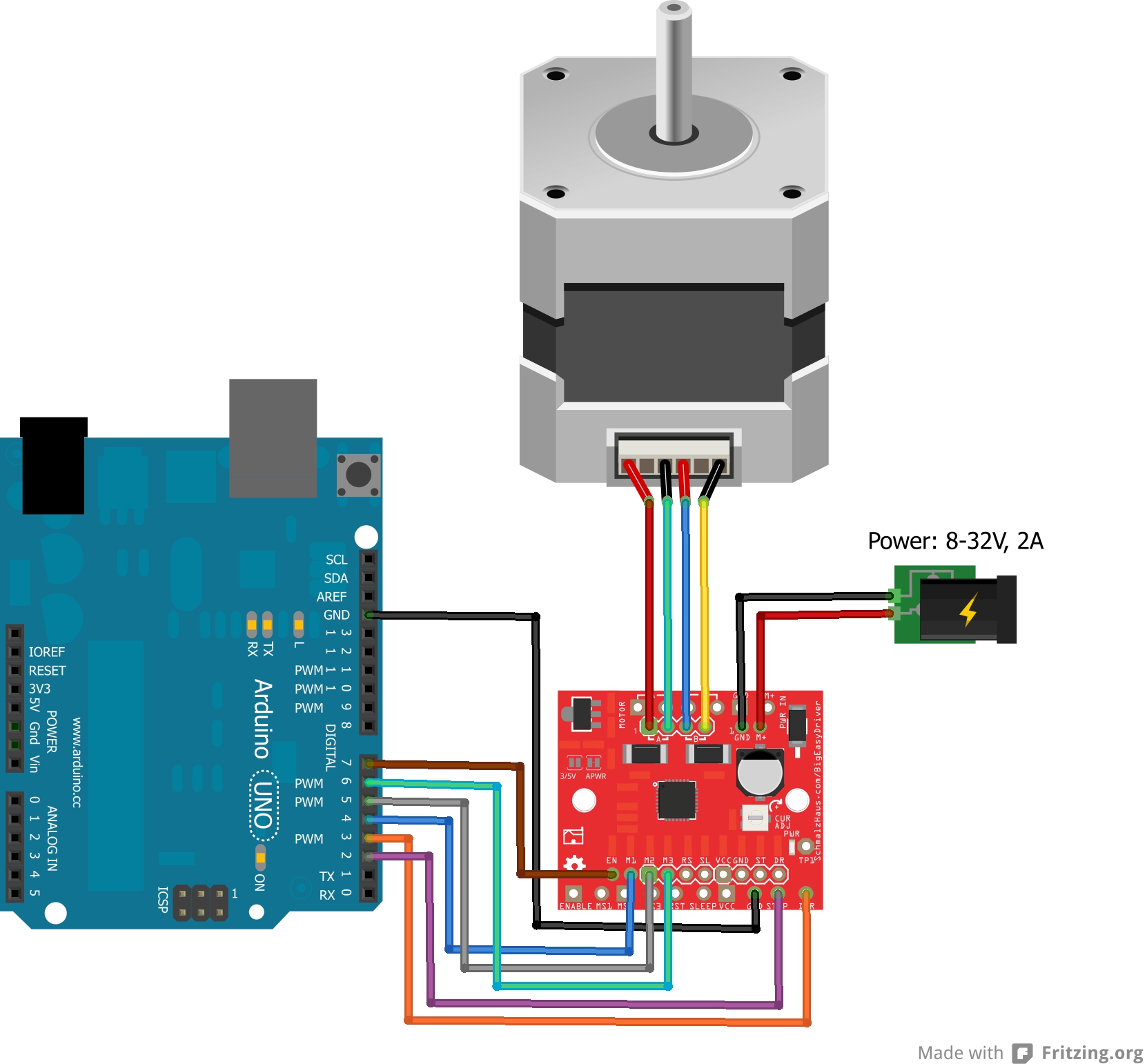
Does this mean that I can use the two lines simultaneously to use two stepper motors with the same controller? Or do I have to use a separate controller per each motor?
But does the driver still have enough current (or power, or voltage, or whatever it is, I'm a total newbie in electronics... ) to drive both the motors? My motors each need 2A/phase, which is the maximum my controller can provide.
Also, I guess this mean they will make steps at the same time, and thus run at the same speed right? If this is the case then I definitely need a second controller...
Leo_:
Does this mean that I can use the two lines simultaneously to use two stepper motors with the same controller? Or do I have to use a separate controller per each motor?
Simple answer - each motor needs its own controller.
If you have two motors that you want to move as one you could wire then in series provided that the total current was within the driver's capacity. This would double the resistance seen by the driver and I think it would also double the impedance which is probably more important. So you would need a higher voltage to get the desired current. Much simpler to give each motor its own controller.