The device is an Arduino DUE. Per a web page I found it has 12 bit A/D but the default is to use a 10 bit mode for compatibility. Fine with me.
Connect the input to ground and get an A/D reading of 0
Connect it to 3.3 volts, 3,330 millivolts (per multi-meter) and the reading bounces between 1021 and 1023. Cool, call it 1022 for 1023 counts.
That is pretty much the max reading for 10 bit A/D.
Divide 3330 millivolts by 1023 to get 3.255 millivolts per count
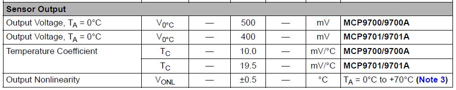
The temperature sensor in use is part number MCP9700A-E/T0-ND. It is a TO-92 package.
I found the spec sheet for
MCP9700/9700A
MCP9701/9701A
It states that at 0 degrees C the output voltage is 500 millivolts.
And the temperature coefficient is 10.0 mV/C.
As I may be reading it incorrectly, that section was captured and will be attached to this post.
Calculate the expected A/D reading for 0 degrees C
500 millivolts * 3.255 counts per millivolt = a count of 153.604 rounded to 154.
If the temperature is 0 degrees C the A/D output should be 154, not counting wobble.
Back to the calculations, use A for the A/D output reading and C for temp in centigrade.
The temperature in C is:
C = ( A – 153 ) ( 3.255 / 10 ) Is this correct?
I run the numbers in Excel for A/D outputs of 0 to 300 and they look ok. Not a guarantee.
Convert to a single slope offset formula.
  C =   ( A – 153 ) ( 0.3255  )

  C =   ( A * 0.3255 ) – ( 153 * 0.3255 )

  C =  ( A * 0.3255 ) – 49.8015   Are these transformations correct?
Add this to the Excel workbook for the range of 0 to 300. Then subtract the former from the latter to get a constant offset of -0.1966. The fact of a constant offset seems really strange. Is there an error in my math, or more properly, my algebra?