Converting Analog ammeter to Digital Meter Using Arduino

I'm currently doing a project to convert an analog ammeter using moving coil for indicator to digital.
The deflection of the needle is depending on the current output that is wired to the meter.
For the needle to fully turn, it requires about 2mA of current. [I tested it by inputting 2mA of current through it externally.]

But when I tested it out while the machine is running at maximum capacity, the current output that is wired to the ammeter is measured at about 40mA.
Any idea why is it like this?

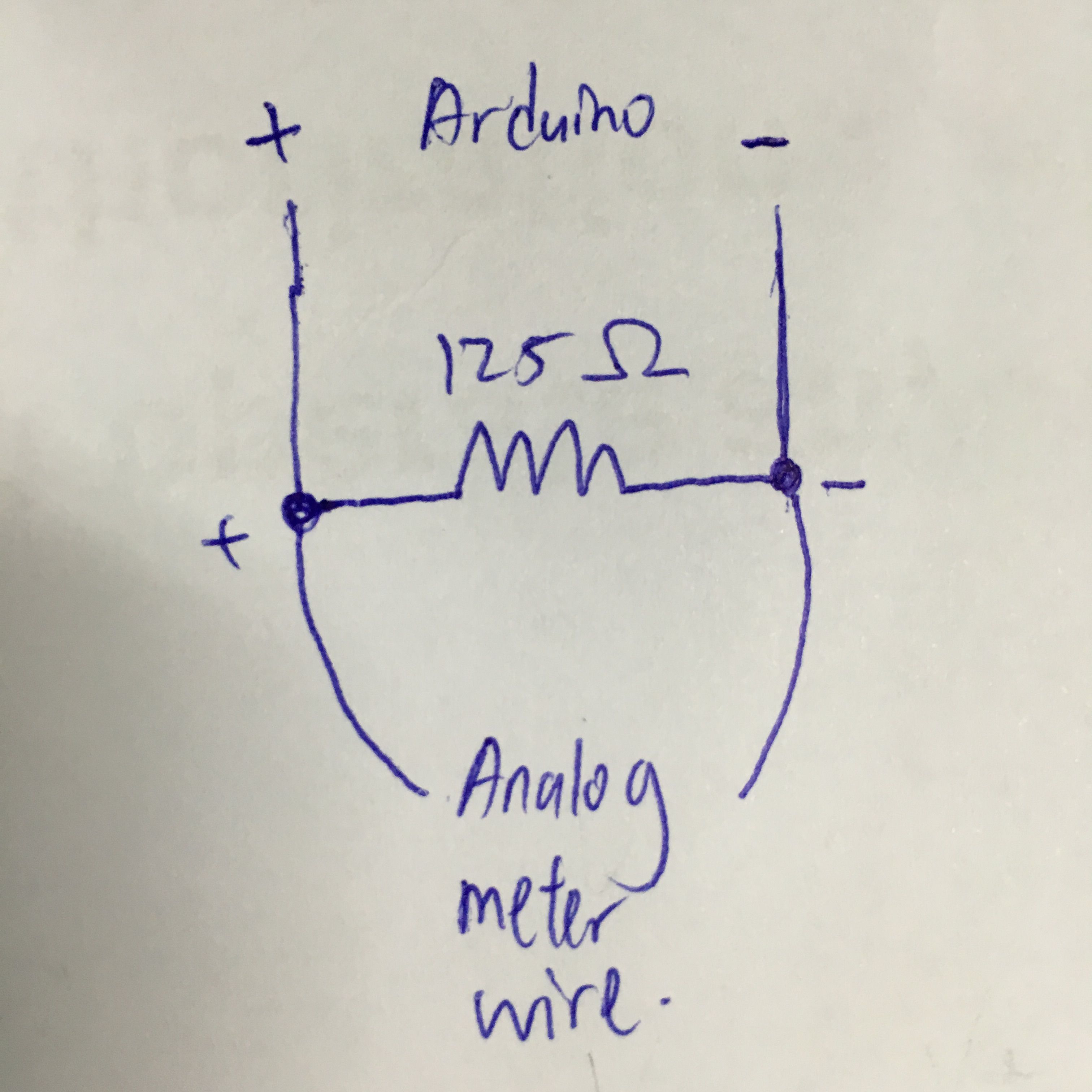
Besides, since Arduino can only takes 0-5V as analog signal. So I try to convert the 40mA to 5V signal by using this approach. Following was my converter circuit diagram:-

+ -
| |
|---[125 Ohm]---| V=IR
| | R=125 Ohm
|[40mA]|

I connect the + to A0 and - to GND of my Arduino, but somehow this approve doesn't work and fried my resistor and resistors.
Any idea what approach can I use other than this?
Thank you.

Hi,

What is the machine you are trying to read current?
Is it AC or DC?

Welcome to the forum.

Please read the first post in any forum entitled how to use this forum.
http://forum.arduino.cc/index.php/topic,148850.0.html.

Can you please post a copy of your circuit, in CAD or a picture of a hand drawn circuit in jpg, png?
In particular the circuit of the assembly you are trying to monitor.
It sounds like the shunt is not at ground potential.

What is your electronics, programming, arduino, hardware experience?

Thanks. Tom.... :slight_smile:

Analog current and voltage meters are the same, they differ only by resistance. What resistance does your meter have?

Are you sure that it's moving coil, not moving iron?

TomGeorge:
Hi,

What is the machine you are trying to read current?
Is it AC or DC?

Welcome to the forum.

Please read the first post in any forum entitled how to use this forum.
http://forum.arduino.cc/index.php/topic,148850.0.html.

Can you please post a copy of your circuit, in CAD or a picture of a hand drawn circuit in jpg, png?
In particular the circuit of the assembly you are trying to monitor.
It sounds like the shunt is not at ground potential.

What is your electronics, programming, arduino, hardware experience?

Thanks. Tom.... :slight_smile:

It's DC.
It's a out-dated power supply unit, so I dont have the circuit diagram with me.

I'm wondering what went wrong or is my current to voltage converter is not wrong?
My experience on this matter is newbie.

Thanks Tom!

DrDiettrich:
Analog current and voltage meters are the same, they differ only by resistance. What resistance does your meter have?

Are you sure that it's moving coil, not moving iron?

I measured the resistance is about 5.22k Ohm.
Speaking of this, I'm not really sure what type of meter is it. I saw NFe behind the analog meter, is it suppose to mean that it's a moving iron?
Anyway, how to distinguish between these 2?
Thanks!

Hi,
What voltage is the power supply?
Does it have a brand and model number?

Can you post a picture of it please?

The current shunt my be on the HIGh rather than the LOW side of the output.
Is the supply a regulated supply?

Sorry for all the questions, but power supplies can be very different from each other.

Thanks.. Tom... :slight_smile:

TomGeorge:
Hi,
What voltage is the power supply?
Does it have a brand and model number?

Can you post a picture of it please?

The current shunt my be on the HIGh rather than the LOW side of the output.
Is the supply a regulated supply?

Sorry for all the questions, but power supplies can be very different from each other.

Thanks.. Tom... :slight_smile:

The power supply is exactly as this 1 on ebay.

I tried to search the circuit diagram online, but no luck in getting that...
Thank you Tom!

So where are you trying to measure the current, is it one of those meters in the supply?

Your description of the wiring is very vague. What about the grounds? A high sided current measurement will require that the Arduino floats with respect to the system you are measuring. That means either operating it off batteries and not connecting it to a computer plugged into the mains. Or an isolated USB cable.

cullen197:
I measured the resistance is about 5.22k Ohm.
Speaking of this, I'm not really sure what type of meter is it.

Moving iron meters measure both DC and AC. I.e. regardless of the polarity of the current, such a meter will always show positive (RMS) values. That's almost their only advantage, and they are rarely used nowadays.
Moving coil meters instead try to show values below zero, when fed with wrong polarity.
If your device is a power supply, we'll have to deal with DC only.

You can keep the old meter in place, or replace it by a resistor of exactly the same resistance. Otherwise you risk malfunction of the device, at least wrong readings.

Direct connection to an Arduino is critical, as you may have found out. In detail the Arduino (or whatever circuit) must be powered by a fully isolated source (battery or wall wart), and should never be connected to other devices, not even by USB! Also protective resistors, of about 10k, should be inserted into the Gnd and signal lines to the Arduino.

Now it looks like a stupid idea, to add another power supply to a power supply, in order to only replace an existing analog meter. That's correct, but it is as it is. The only way around an additional power supply is the use of the unregulated voltage of the device itself. Eventually you can attach an isolating step-down converter to it, in order to provide floating power to the Arduino.

But even then the Arduino must never be connected to some other circuit, or you risk to blow your power supply. Unless you use e.g. optocouplers or a wireless module, to isolate serial data lines for data transmission.

Sorry to say, but your project will be more instructive than really useful. Even if you use a ready-made digital ammeter, you'll have to power it from a fully isolated power source.

Hi
The OP power Supply
Shibaura Nmp-0301-b Rf Power Supply & Nmb-030 1,557khz


Tom... :slight_smile:

Hi,
Do you have an operators manual, and what do you want to do with it?
What is its output voltage, the fact that it says RF has me worried about what it is actually capable of.

Tom.... :slight_smile:

Grumpy_Mike:
So where are you trying to measure the current, is it one of those meters in the supply?

Your description of the wiring is very vague. What about the grounds? A high sided current measurement will require that the Arduino floats with respect to the system you are measuring. That means either operating it off batteries and not connecting it to a computer plugged into the mains. Or an isolated USB cable.

I'm trying to convert all the analog meters.
Following pictures are the back of the meters. One of the meter has a diode attached with it.


My wiring for this is as shown in the pic

What do you mean by Arduino floats?
You dont mean the data type of float right?
I power up my Arduino externally by connecting it with USB cable to my laptop.

Thank you.

What do you mean by Arduino floats?

That the Arduino system is isolated from your power supply.

I power up my Arduino externally by connecting it with USB cable to my laptop.

That is why your resistors burned out.

But with three meters to monitor, each connection needs to be isolated not only from the power supply but also from each other.
Maybe a flying capacitor isolation circuit might work?

TomGeorge:
Hi,
Do you have an operators manual, and what do you want to do with it?
What is its output voltage, the fact that it says RF has me worried about what it is actually capable of.

Tom.... :slight_smile:

I do not have the manual and couldnt find it online too, I just wanted to monitor the meter online using arduino + xbee.

Grumpy_Mike:
That the Arduino system is isolated from your power supply.
That is why your resistors burned out.

Meaning I couldn't power my Arduino using USB connection?

Grumpy_Mike:
But with three meters to monitor, each connection needs to be isolated not only from the power supply but also from each other.
Maybe a flying capacitor isolation circuit might work?

You mean I could only monitor 1 meter with 1 Arduino and requires 3 Arduino to monitor all the 3 meters?

Hi,

What do you want to do with it?

What is your electronics, programming, arduino, hardware experience?

Tom.... :slight_smile:

Meaning I couldn't power my Arduino using USB connection?

Yes unless the USB has an isolated lead or the inputs are not referenced to the ground on the power supply.

You mean I could only monitor 1 meter with 1 Arduino and requires 3 Arduino to monitor all the 3 meters?

Yes, unless again you have isolated each input's referenced level from each other. This is why I said:-

Maybe a flying capacitor isolation circuit might work?

But those need relays and a change in the relay contacts is needed for each reading, so you can't read it very fast.

I had inquired about the detail of the meter from its maker. They replied it's a moving coil meter and basic range of the meters are DC 5 volts.

So can I tap a wire parallel-ly from the meter itself to the Arduino board A0 and GND to measure it digitally?

Hi,
Can you please answer post #15 please.
Also do you know what its output voltage is, this looks like a serious piece of professional broadcast gear.

Do you know what this piece of equipment does?

Tom.... :slight_smile:

So can I tap a wire parallel-ly from the meter itself to the Arduino board A0 and GND to measure it digitally?

No.

Have you understood nothing of what I have told you?