At the beginning, you didn't have a question about converting 0-3V to 0-24V.
This is a completely different question.
Probably it would be necessary to open a separate topic.
Although you did not specify the requirements for a 0-24V signal, I see that this can be solved in several ways.
Okay so in this topić i will continue when i build the op amp for analog output.
I will Create a new topić for digital outputs. Anyway the previous post with the LM339 wont work ?
Okay So my DAC will give maximum about 3/3.3V, let's say that it is 3.3V.
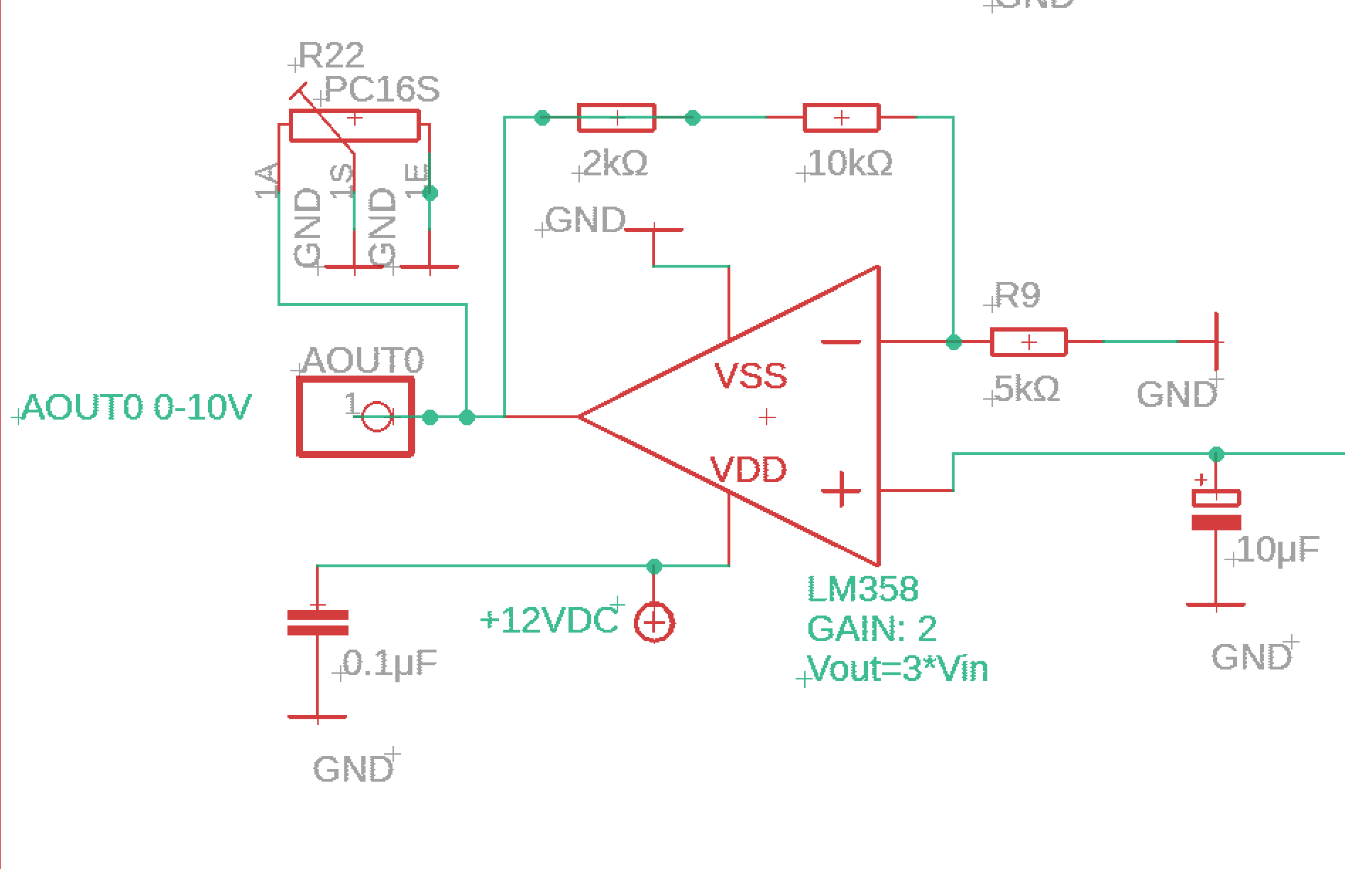
So to create an op amp with LM358 I need to get a gain of 3.
If I use the NON inverting inputs :
I need to put R1=100 Ohm
R2=200 Ohm for example, and that is enough ? Or do I need some capacitors also ? And also is it better to use 100Ohm and 200Ohm or 1kOhm and 2kOhm?
And what with the supply of the op amp, is it okay to supply it with 3.3V ? Or it is better to use 12V which are supplying the due ?
I think i should ( I must ) put 3.3V at the Vin but supply it with 12V.
I gave you the answer in post #9 and #18.
As long as there is an LED on the Aout, I can't give any more advice.
The LED is a high-current load for this DAC, and a highly non-linear load.
Why do you need such a DAC, I do not understand.
The value I receive in a program is from 0-100. The dac converts it to 0-3.3V and I want to convert it to 0-10V to be usable by a PLC analog input.
No LEDs here, only in digital outputs.
Ah you mean the LED in PCF8591?
I will unsolder it
I did an op amp like I said but I used 5k and 10k Resistors.
I used UNO 3.3V as an input and when supplying it with 12V the output is 10V so good.
But when I take the input off (the 3.3V) it is still 10 V
When I take the supply (12V) off it is 0V.
The PCF8591 module has an 8-bit DAC. He has Vref = Vcc. If the supply voltage = 3.3V, then for values 0-100 you will not get 0-3.3V, but only 100/255 * 3.3 = 1.29V.
I didn't understand what that means. Which input do you off.
The PCF8591 receives commands from Arduino via the I2C bus and stores them in an internal register. If you disconnect the I2C bus, the DAC will save the value at the output. But what do you do that for?
If you turn off the power supply 3.3, but leave 12V, then why are you doing this?
I mean that in built op - amp I have
IN + 3.3V from Arudno uno 3.3v supply ( just for test)
Vcc=12V
When i measure the output OUT1 it is about 10V so it looks like it works, but if I unplug the IN+ (3.3V) the output is still 10V so somethings wrong because it should be about 0 so If i plug in the signal from DAC it will change proportionally
I think I need to add some extra Resistor between the IN (3.3V) and GND .
I cannot understand why you are disconnecting the input.
The op-amp cannot work with the input disconnected. Connect it to PCF8591 and forget.
If you want to test the op-amp, connect a potentiometer to the input.
Okay burnt one LM358 but on another one finally I did it
Addes also the capacitors ( I guess it's for stability ?). The gain is excactly 2.96x so I have a pretty nice converter but I think that I should add maybe another 1,5k in series with 10k resistor to make the gain closer to 3.33. so it goes for almost 10V when it's maximum.
Why do you ask questions if you do not read the answers? Tell me honestly, have you read the article in post # 9? It contains a diagram in fig. 1 with variable gain.
Never draw diagrams the way you do. Signals must be transmitted from left to right. Element's inputs are on the left side and outputs are on the right.
Yes I read the answers, I know that I should add it in series with R2 (10k) but I do not know how to connect it
When I tried to conect it the gain varies from min to max so from gain 1 to gain 3.
I want to use the 1k potentiometer to make the precise change like the gain sets the max output for 9,7V and i use it to get it to 10,0 V .
How can i conect the P1 in series with for example R2 to adjust R2 to 5-6k? I mean there are 3 pins of the P1 1. GNS 2. OUT 3. IN
which one I should put where?
Okay i tested it and now my gain range is 1-3.3 ( I need that because if Due will give for example 3V (not 3.3V) i will still scale it to 0-10.
And I added the potentiometer so i can scale the gain: