Hi,
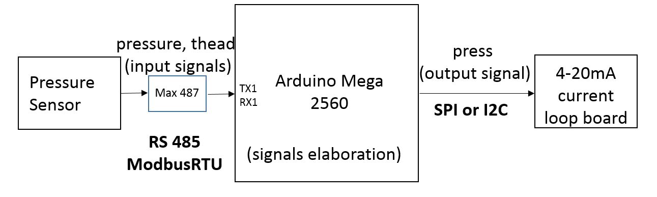
I am controlling a pressure sensor using an Arduino Mega 2560.
Arduino behaves as a master and the communication is via RS485 half duplex and the protocol will be Modbus RTU.
The program attached works fine for me.
#include <SimpleModbusMaster.h>
#include <stdio.h>


/////////////////// Port information ///////////////////
#define baud 9600
#define timeout 200
#define polling 1000 // the scan rate
#define retry_count 5

// used to toggle the receive/transmit pin on the driver
#define TxEnablePin 8

#define LED 9

// The total amount of available memory on the master to store data
#define TOTAL_NO_OF_REGISTERS 2

// This is the easiest way to create new packets
// Add as many as you want. TOTAL_NO_OF_PACKETS
// is automatically updated.
enum
{
  PACKET1,
  TOTAL_NO_OF_PACKETS // leave this last entry
};

// Create an array of Packets to be configured
Packet packets[TOTAL_NO_OF_PACKETS];

// Masters register array
unsigned int readRegs[4];   //Data read from the slave will be stored in this array


float pressure;
float thead;
float press;

/calibration parameters
const float c= 0.025;
const float d= 0.072;
const float e= 0.422;
const float f= 0.431;


void setup()
{

  // Initialize each packet
  Serial.begin(9600);
  Serial1.begin(9600);

  modbus_construct(&packets[PACKET1], 250, READ_HOLDING_REGISTERS, 0x100, 4, 0);
  modbus_configure(&Serial1, baud, SERIAL_8N1, timeout, polling, retry_count, TxEnablePin, packets, TOTAL_NO_OF_PACKETS,readRegs);   // Initialize the Modbus Finite State Machine

  pinMode(LED,OUTPUT);
}


void loop()
{

  delay (100);
  modbus_update();

  digitalWrite(LED, HIGH);
  delay(100);
  digitalWrite(LED, LOW);

  //Shift and Cast pressure to float
  unsigned long temp1 = (unsigned long) readRegs[0] << 16 | readRegs[1];
  pressure = *(float*)&temp1;

  digitalWrite(LED, HIGH);
  delay(100);
  digitalWrite(LED, LOW);

  //Shift and Cast value tempretaure to float
  unsigned long temp2 = (unsigned long) readRegs[2] << 16 | readRegs[3];
  thead = *(float*)&temp2;

 //Calcultion of press
  p = pressure;
  p2 = pow (p,2);
  p3 = pow (p,3);


  press = c * p3 + d * p2 + e * p + f;

  Serial.print("\nRequestspack: ");
  Serial.println(packets[PACKET1].requests);
  Serial.print("Successful requestspack1: ");
  Serial.println(packets[PACKET1].successful_requests);
  Serial.print("Failed requestspack1: ");
  Serial.println(packets[PACKET1].failed_requests);
  Serial.print("Reg[0]: ");
  Serial.println(readRegs[0]);
  Serial.print("Reg[1]: ");
  Serial.println(readRegs[1]);
  Serial.print("pressure:");
  Serial.println (pressure,4);
  Serial.println("");   // new line
  Serial.print("Reg[2]: ");
  Serial.println(readRegs[2]);
  Serial.print("Reg[3]: ");
  Serial.println(readRegs[3]);
  Serial.print ("thead: ");
  Serial.println (thead,4);
  Serial.println("");   // new line
  Serial.print ("press: ");
  Serial.println (press,4);
  Serial.println("");   // new line

}
As you can see, I use the Serial1 for the the sensor's communication and Serial to monitor the sensor's outputs with the pc display.
The next step for me is to convert the format of the outputs 4-20mA. Do you have any suggestions about how to do that from the HW and FW points of view?
Thank you in advance.