Correct power/voltage supply for Arduino Nano and L298N

Hi there,

(First of all, I would like to apologize if this isn't the correct category for my actual problem - and also if this question of mine happens to be downright simple)

I am basically developing a project with the use of an arduino nano, a L298N driver, 2 DC motors and a 4-AA battery holder. On the baterry holder, each battery is supposed to provide 1.5V, so with 4 of them the total voltage should be around 6V.

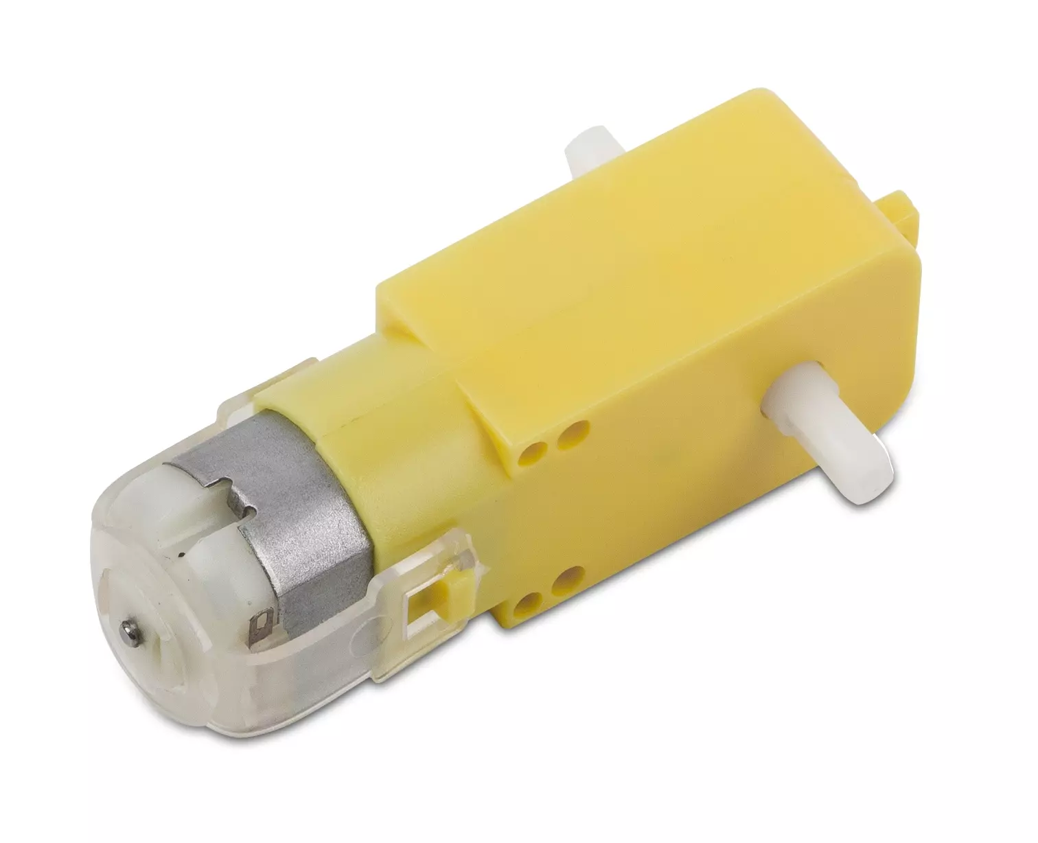
Since I do not know how to draw a sketch, I will try to describe the connections here: currently, the 6V from the battery holder supplies both the Nano's Vin and the L298N's pin identified as "+12V", but I've also connected the Nano's 5V pin to the "+5V" pin from the L298N (with the L298N's 5V regulator jumper removed). Please have in mind that I am unfortunately a newbie on arduino development, so I do not know if this setup would be actually the correct one. Also, I am using this model for the 2 DC motors.

Here is my current problem: after some time using the same batteries for this project, I've noticed that the 2 DC motors started to behave strangely (one would start operating before the other, and sometimes they would not operate at all when they were supposed to). After checking that the voltage supply have dropped to 5.7V, I've decided to substitute the batteries for 4 new ones and after that everything went back to normal.

In order to avoid the need to substitute the batteries too much frequently, I've started to consider using a 8-AA battery holder (which should supply around 12V). I’ve managed to do some research regarding the maximum allowed voltage for the Nano’s Vin, but some resources stated that the range would be from 7 to 12V, while others stated that it would be something like 6-20V.

Also, I’ve checked the L298N datasheet and discovered that the maximum supply voltage for the +12V pin would be quite high, however a friend of mine told me that if I delivered 12V to the L298N, it would deliver 12V to the 2 DC motors and thus both would be "toasted" (since they are supposed to operate with 3-6V). I’ve asked him if the L298N wouldn’t have some kind of internal voltage regulator for the DC motors, however he wasn’t sure about that (and I couldn’t find any info related to that as well).

Should I keep using the 4-AA battery holder instead of the 8-AA one? If it is actually possible to substitute to the 8-AA, would there be the need for me to implement any kind of modification to my protoboard/driver/code? Any kind of advice here will be very much appreciated!

You do know how to use pen and paper? Then make a close photo and post it.
Reading "word sallad" forces helpers to make drawings, and we, generally, don't do that. The result is either no replies or useless guesses.
Posting Your guesses, friends guesses, or street talking tells us nothing. We don't don't need guesses to choose among. It only makes a lot of tiring text to read.

Would a photo of my project be enough, or would it be better if I provided a pen and paper drawing?

Please make a pen and paper drawing. Photos often look like a spiders nest.

Please let me know if it is clear enough...

So far, yes.
I'm no expert on nanos, only used UNOs. From that I wonder if 6 volt to nano Vin is enough. UNOs need 7.5 - 12 volt.
Any decoupling capacitor near the L298N? Some 100 - 1000 microfarad?
Post a link to the motors. 2 motors and only AA batteries sounds like eating batteries.

Sorry, but do you mean a "built-in" decoupling capacitor on the L298N driver or a "separated" capacitor (that would be somehow connected to the L298N) ?

Also, what kind of link for the motors? Would you like a photo of mine or a link containing major info regarding these motors?

I think about an extra, external, additional capacitor. It very much depends on the motors.

A link to the data sheet of the motors, not any sales site telling the price....

I have an "unofficial" datasheet with me, but since I still can't send the pdf file here, I will paste the copied text and send some figures:

DC Gearbox Motor - "TT Motor" -
200RPM - 3 to 6VDC

Perhaps you've been assembling a new robot friend, adding a computer for a brain and other fun personality touches. Now the time has come to let it leave the nest and fly on its own wings– err, wheels!

These durable (but affordable!) plastic gearbox motors (also known as 'TT' motors) are an easy, low-cost way to get your projects moving. This is a TT DC Gearbox Motor with a gear ratio of 1:48, and it comes with 2 x 200mm wires with breadboard-friendly 0.1" male connectors. Perfect for plugging into a breadboard or terminal blocks.

You can power these motors with 3VDC up to 6VDC, they'll of course go a little faster at the higher voltages. We grabbed one motor and found these stats when running it from a bench-top supply

At 3VDC we measured 150mA @ 120 RPM no-load, and 1.1 Amps when stalled
At 4.5VDC we measured 155mA @ 185 RPM no-load, and 1.2 Amps when stalled
At 6VDC we measured 160mA @ 250 RPM no-load, and 1.5 Amps when stalled

Note that these are very basic motors, and have no built-in encoders, speed control or positional feedback. Voltage goes in, rotation goes out! There will be variation from motor to motor, so a separate feedback system is required if you need precision movement.

Comes 1 x per order, with just the motor + wires. You cannot drive these directly from a microcontroller, a high-current motor driver is required! We recommend our DRV8833 motor driver for these motors, as it works well down to 3V and can be set up with current limiting since the stall current on these can get high. The TB6612 can also be used, it's on our shields and wings, but you'll need to supply at least 4.5V - which is what you'll likely want to run these motors at anyhow!

We have a range of wheels, add-ons and accessories for these motors so you can bling out your bot just the way you like.

TECHNICAL DETAILS

Rated Voltage: 3~6V
Continuous No-Load Current: 150mA +/- 10%
Min. Operating Speed (3V): 90+/- 10% RPM
Min. Operating Speed (6V): 200+/- 10% RPM
Torque: 0.15Nm ~0.60Nm
Stall Torque (6V): 0.8kg.cm
Gear Ratio: 1:48
Body Dimensions: 70 x 22 x 18mm
Wires Length: 200mm & 28 AWG
Weight: 30.6g
Product Weight: 30.6g / 1.1oz

(Oh yes, I've forgot to mention that there isn't any kind of (external) capacitor being used on my circuit/project)

Okey, thanks.
No exceptional motors. My suggestion is that the power supply, using AA batteries, is not powerful enough.

What is Your demand for run time of the setup? I would think the batteries would last for minutes, not hours.

Again, check the Vin demands for the nano. It looks like running from 4 AA. Using 8 AA does not increase the current capacity of the AA pack.

Can You get hold of a more capable power supply?

For the time being, since this is supposed to be only a college project, I believe there would be nothing in particular for the demanded run time (however, I guess it would be nice for the run time to be as high as possible if I decide to provide it as a product or whatsoever in a near future).

I guess that the 4AA voltage supply for the Nano's Vin is actually pretty ok (my project is working as expected, however I've wanted to use a more powerful voltage supply, so that the minimum required voltage/current for the motors could be provided from the L298N for a longer time before the batteries weared out to an insufficient supply voltage. By using more batteries, it seemed quite obvious to me that it would take much longer before having the need to substitute the used batteries - however, my problem is that I wasn't sure about doing that because of the possibility of damaging the DC motors).

When you say "a more capable power supply", do you actually mean something like a USB Power Bank?

Why guess? Arduino publishes the specification on the product information pages.

1 Like

They are limited to 5 volt output. Some gives only 1 Amp, some gives more.
Using the stone age, voltage wasting, L298N there's less voltage available for the motors. The performance will be less good. Useful or not? I can't tell.
Better would be to use a MOSFET based driver.

"I guess" was just an expression (and not an assumption of mine based on absolutely nothing).

Indeed, those specifications are provided on the information pages, however they seem to be conflicting in some cases (I am not posting the link here - even though it is from arduino itself - due to the fact that it contains a selling price, but this very same page related to the Nano model informs that the range for Vin is both 7-12V AND 6-20V).

Which MOSFET based drivers do you recommend the most?

Do you have soldering equipment and the ability to use it?
https://www.pololu.com/product/713

Sort of… thanks very much for the link!

Well, an elucidation of that would have avoided the misunderstanding. Information from a third party site that I can't see, isn't much use in resolving any conflicting information. I think it would be wise to accept the official Arduino specification. I don't think there is any ambiguity about that.

Many third party vendors exaggerate the specifications or get them dead wrong, so I don't generally believe those.

Third party boards that use different components have to be evaluated from scratch on a one-one basis, either by reading components or finding a schematic somewhere (good luck).

The “double” info regarding the voltage supply range I’ve mentioned was NOT from a third-party site:

https://www.arduino.cc/en/pmwiki.php?n=Main/ArduinoBoardNano

Take a look at the “Technical specs” table and also on the “power” section under “Documentation”. I am sorry, but If you don’t find it ambiguous, then perhaps I don’t know what “ambiguity” actually means.