Couple of questions - wiring up 3 parallel sets of 2 serial strips

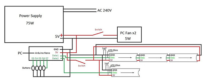
Complete beginner here. I've been reading through the forum and have looked for projects similar to the one I'm starting on. I found Multiple led stips from one Arduino to be most similar and so am working to understand that. I have a couple of questions which I'd be grateful for help with. The final diagram in that referenced post looks like this:

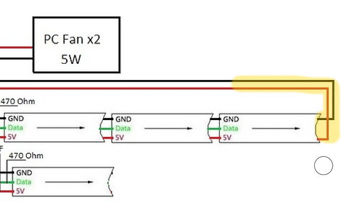
The diagram shows 3 serial LED strips and a single parallel one. I'm curious to understand why the power line on the 3 serial strips goes back, whereas it doesn't on the parallel one. Why is this required in one case and not the other?

To make it clearer; this - why is this required?

My second question regards the 1mF capacitor - I'm not exactly sure what I need to buy nor how to wire that in so I need a bit of advice on that please. I'm guessing I don't solder it directly to the LED strip but instead across the black/red wires ahead of the strip somewhere.

My own project will have 3 parallel sets of 2 strips in series. I'm making sure I get it wired up correctly before I start breaking things!

Thanks for any help

1 Like

Welcome to the forum

When using a series of addressable LED strips fed with power from one end it is possible that the voltage drop along the length of the combined strips could be such that the operation of the later LEDs is affected.

To alleviate this, power can be fed to both ends or intermediate positions along of the combined strips. This is probably why the diagram shows this

1 Like

1000uF electrolytic. Solder the capacitor + to VCC and - to GND of the RGBLED strip. This is for power smoothing. Don't forget the 470R resistor on the data pin, also for surge suppression.

And for preventing reflections on the line, which can destroy the signal integrity.

1 Like

@bazzza This Adafruit guide is a pretty good place to start

Thanks to you all - that's clarified it for me. That Adafruit guide is a really useful reference.

I'm looking to power 10m with 5 volts, 30 LEDs per metre at max 0.3W/LED, so I'm looking for a power supply to support that - I welcome any recommendations as my searches are coming up with many options and I don't know how to choose. Cheers.

That would be 30 * 10 = 300 LEDs. And as a working figure allow 60mA per LED, so that would be a current capacity of at least 18A. I say at least because you should never run any component at its full rating, normal practice is to de-rate at 80%.

Remember even an LED that is off will draw about 1mA. So that is 0.3 Amp before you start.

I think this is wrong, these strips don't have LEDs that consume such a high current.

Thanks Grumpy_Mike. Here's my reference: SK6812(Similar WS2812B) RGB+Pure White 4IN1 Individual Addressable Dre – BTF-LIGHTING

'30LEDs/meter ---------9W / Meter'

I have no experience to allow me to doubt what it says

Full power from these LEDs is quite theoretic because of the already mentioned voltage drop. It's around 1V/100LEDs
If you want to get anywhere near to full power, you need to power the strip not only from beginning and end, but also between.
On the other hand, in most cases full power is not needed. It's your choice (on your code) how bright you want to drive them.I have 300 led strip and WLED running nice effects with 2A power supply.
But if all LEDs simultaneously at max power is your target, you need >20A PSU for 300LED setup.

It would have been good to know this from the start. It is nothing like the WS2812, you lead us to believe you had.

That link tells us nothing about you address the white pixels in it. So if you know how to drive these let us know. The problem this is an LED lighting company and not an electronics company so they normally know nothing technical about them, like timing diagrams.

I had no intention to mislead! It's all up for grabs - I'm just looking for the best solution and I hadn't really made any decisions. If that's a poor choice, I welcome a better suggestion as I haven't bought anything yet.

As I said, I found an article here which seemed to have similarities to what I'm trying to achieve and so am working from that.

Best tech data sheet for something akin to these is this one:

which makes reference to 24 bit transmission(rehash of standard RGB strings), pretty much standard 800 kHz clocking, but then on page 4 shows a data transmission of 4 bytes, the 4th of which sets the white brightness. No guarantee this data sheet relates to our OP's product, but it would seem like you need a library that does RGBW, or GBRW - at least, sends 4 bytes per pixel.
Good luck!

It was never shown that it was necessary. The OP never said that his set-up ever worked. One of his diagrams had power supplied to each strip.

Whether you need multiple power connections and the 1000uF cap will depend on your particular set-up

Thanks for the pointer on this. I asked them and they replied:

'the SK6812 led strip can work with the Arduino. However, our technicians feedback that this operation is difficult, may be have more prone to problems. We recommend you can use our matching controller to control our led strip products.'

Looking elsewhere, ensuring the supplier mentions these concerns. Considering this one Flexible RGBW LED Strip (NeoPixel/WS2812/SK6812 compatible) - 30 LED/Metre | The Pi Hut

I came across some assertion that there is a strip with three different color temperature white LEDs on each pixel, these would be driven by using R, G and B to control each element.

Here do we have R, G, B and a fourth W LED?

Adafruit's NeoPixel library does WRGB 32 bit pixels.

a7

Absolute rubbish, they are just trying to sell you more stuff. I have extensively used these strips and found them to be very reliable.

Most of this has been under Python in my book :-

https://www.oreilly.com › library › view › raspberry-pi-for › 9781119796824

But I have also written some bit banging code for the Arduino to drive them.

// Bit banging a DotStar/APA102/SK9822 
const int8_t numLeds = 26; // Change to how many LEDs you have
uint32_t ledArray[numLeds]; // buffer to hold LED data
uint16_t ledArray1[numLeds];
uint16_t ledArray2[numLeds];
int8_t dataPin = 13 ; // Change to the pin you want to use
int8_t clockPin = 12 ; // Change to the pin you want to use
uint8_t bright;  // default brightness use function to change this

void setup() {
  pinMode(dataPin, OUTPUT);
  pinMode(clockPin, OUTPUT); 
  setBright(18); // brightness for LEDs
  for(int i=0; i< numLeds; i++){ // initilise LED brightness
    ledArray[i] = bright << 24;  
  }
  //wipe(0, 0, 0); // turn all LEDs off
  Serial.begin(9600);
  delay(1000);
  Serial.println("start of code");
  setPixelColour(0, 0x10, 0x30, 0x60);
  Serial.println(ledArray1[0] ,HEX);
  Serial.println((ledArray2[0]),HEX);
  
}

void loop() {
  
  wipe(0x20, 0x20, 0x20);
  //Serial.println("loop");
  setPixelColour(3, 5, 0, 0);
  setPixelColour(6, 0, 5, 5);
  delay(200);
  wipe(0, 0, 0);
  delay(800);
  
}
//////////// LED colour manipulation functions //////
void setBright(uint8_t val){ // set brightness from 0 to 31
  if(val > 31) val = 31;
  if(val < 0 ) val = 0;
  bright = val | 0xE0;
}

void wipe(uint8_t r, uint8_t g, uint8_t b){ // set all colours the same and show
  for(int i=0; i< numLeds; i++){
    setPixelColour(i, r, g, b);
  }
  //Serial.println("set colours");
  pixelsShow();
}

void setPixelColour(uint16_t num, uint8_t r, uint8_t g, uint8_t b){
  if(num < numLeds && num >= 0){
    ledArray1[num] = (bright<<8) | b;
    ledArray2[num] |= (g<<8) | r;
   // Serial.println(num);
  }
}
//////////// Data transfer functions /////////
void pixelsShow(){ // send buffer to the hardware
  uint32_t data = 0;
  uint32_t mask = 0x80000000UL;
  sendHeader();
  // for(int i=0; i<numLeds; i++){
  for(int i=0; i<numLeds; i++){  
    data = ledArray[i];
    mask = 0x80000000UL;
    for(int j=0; j<32; j++){ // output the LED data
       //digitalWrite(clockPin, LOW);
       PORTB = PORTB & 0xEF;
       if(data & mask) {
          //digitalWrite(dataPin, HIGH);
          PORTB = PORTB | 0x20;
     }
     else {
         //digitalWrite(dataPin, LOW);
         PORTB = PORTB & 0xDF;
     }
     mask = mask >> 1;
     //digitalWrite(clockPin, HIGH);
     PORTB = PORTB | 0x10;   
   }
  }      
sendFooter();
//digitalWrite(dataPin, LOW);
PORTB = PORTB & 0xDF;
}

void sendHeader(){
  //Serial.println("send header");
//digitalWrite(dataPin, LOW); // set data pin low
PORTB = PORTB & 0xDF;
for(int i = 0; i< 32; i++){
  //digitalWrite(clockPin, LOW); // pulse the clock pin
  PORTB = PORTB & 0xEF;
  //digitalWrite(clockPin, HIGH);
  PORTB = PORTB | 0x10;
   }
}
  
void sendFooter(){
  //digitalWrite(dataPin, HIGH);
  PORTB = PORTB | 0x20;
  //for(int i = 0; i< (33 + (numLeds>>1)); i++){
  for(int i = 0; i< 1 + numLeds>>1; i++){  
     //digitalWrite(clockPin, LOW);
     PORTB = PORTB & 0xEF;
     //digitalWrite(clockPin, HIGH);
     PORTB = PORTB | 0x10;
  }
  //digitalWrite(dataPin, LOW);
  PORTB = PORTB & 0xDF;
}

Never had any problem on either platform.
You can easily bit bang the APA type smart LEDs, it's just clock and data.

The WS2812 and its ilk are different, using one data line with timed pulses, interesting but kinda hard to do at the digitslWrite or the direct port equivalent level of coding.

The timing is critical but the data sheet is misleading:

HTH

Anas Kuzechie explains NeoPixel using Assembly...

This topic was automatically closed 180 days after the last reply. New replies are no longer allowed.