OK. Please forgive me if this next bit is too elementary. Your technique for measuring current seems to be reasonable. However, you don't explicitly say that you disconnected all the LED wires from the power supply before connecting the meter between the power supply and all of the wires that serve LEDs. Two things could have gone wrong: if you didn't disconnect the supply from the LED wires, then most of the current goes around the meter, through the existing connection, and the meter can't see most of the current. If you did disconnect, but didn't connect all the LED wires to the meter, then you're only measuring part of the current that drives the LEDs. Again, I apologize if that's too elementary. It's hard to get a handle on your skill level - it seems to be more than adequate for this project, but you claim to be a neophyte.
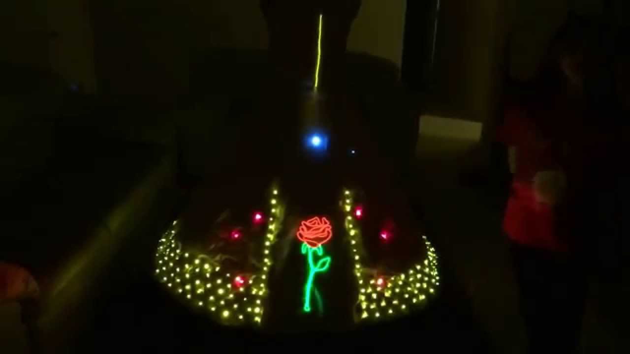
I don't see voltage measurements across some of the warm white LED resistors. By my calculations, each of those LEDs would draw close to 20 milliamps - (4.5V - 3.1V) / 68 Ohms = 0.0205 Amps, or 20.5 milliamps, with a theoretically perfect battery; with a real battery, it'll be something less. So, the roughly 400 of them that I estimate should draw about 8 amps from an ideal power supply. I'm presuming a voltage drop of 3.1V across the warm white LEDs. I can't see the resistors clearly in the photo, but they look to be consistent with 68 Ohms, which would have color bands blue, grey, black. If the resistors were something larger than 68 ohms, that would explain a lower-than-expected current reading, at least in part.
I'm presuming that the warm white LEDs aren't driven by a Lilypad, but that their resistors are directly connected to the power supply.
24 guage wire is small, but it's resistance is only about 0.14 Ohms per meter in aluminum, and about 0.83 in copper. Worst case, that corresponds to about 0.11 volts for a round-trip of a meter and a half, at a half amp. Not much; that's not it. It's also not making much heat.
The internal resistance of an alkaline C cell is 0.15 to 0.3 ohms; three in series would be about half an ohm to an ohm. That's much more than we can expect from the wire. At half an amp, that yields half a volt to a volt. Worst case, the voltage drops as low as maybe 3.4 volts for a new set of batteries. if the typical warm white LED voltage is 3.1 volts, the current will be (3.4 - 3.1) / 68 = 1.7 amps; at 3.3 volts, the current is close to half an amp. A few voltage readings across some of the 68 ohm resistors in series with the warm white LEDs will go a long way toward verifying this notion, as would a voltage reading across the power supply while the LEDs are illuminated.
Three C cells in series can deliver between five and ten amps to a short circuit, based on Eveready's data for their standard alkaline cell. They'll deliver considerably less to LEDs with a forward voltage drop above 3 volts, as in this arrangement.
Note that a red LED typically has a voltage of about 2 volts. With a 68 ohm resistor, that comes to about 37 milliamps. I can't speak to the Lilypad particularly, but the Arduino Uno likes to keep its output current at 20 milliamps per pin or below. It looks like all the red LEDs are on for a brief time. That may be overstressing the Lilypad, and could lead to early failure. You may want to consider increasing the resistors for the red LEDs to 150 ohms.
I think that the hottest thing in the costume would be the batteries, which would generate maybe a half watt. Not much; the wearer might welcome it in winter. Still, it's worth testing.
Finally, I'll echo the sentiment of jremington: it's indeed a very nice piece of work.

