I'm quite new to the hole arduino thing but managed to get almost everything working.
Brief explanation:
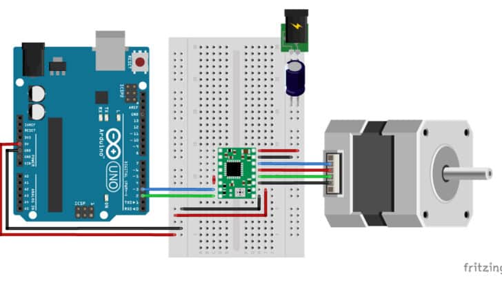
I have an Arduino Nano, with an sct013, when current is detected a stepper motor should “run”.
(The stepper has a lead screw attached which activates the limit switches)
Everything is working as it should if I "fake" the current detection with a normal switch. But when I attached the sct013 to all of it, the stepper barley turns.
I assume that has to do with the "sample size" or the fact that it reads the analog value??
I reduced the sample size from 10,100,500 to 1200 but with not much improvement.
I would be happy about any suggestions.
Here is my code:
#include <AccelStepper.h>
#include "EmonLib.h"
#define CURRENT_SENSOR_PIN A0

EnergyMonitor emon1;

// Define the connections for your stepper motor
const int stepPin = 3;
const int dirPin = 4;
const int enPin = 5;

// Define the connections for your limit switches
const int limitSwitch1 = 7;
const int limitSwitch2 = 8;

const float currentThreshold = 2.0;

// Create an instance of the AccelStepper class
AccelStepper stepper(1, stepPin, dirPin);

void setup() {
  // Set the stepper motor as an output
  pinMode(stepPin, OUTPUT);
  pinMode(dirPin, OUTPUT);
  pinMode(enPin, OUTPUT);

  // Set the limit switches as inputs with pull-up resistors
  pinMode(limitSwitch1, INPUT_PULLUP);
  pinMode(limitSwitch2, INPUT_PULLUP);

  // Set the motor's speed and acceleration
  stepper.setMaxSpeed(1500); // Adjust this to your motor's specs
  stepper.setAcceleration(500); // Adjust this to your motor's specs

  emon1.current(CURRENT_SENSOR_PIN, 111.1);  // Calibration factor may need adjustment
}

void loop() {
// Measure current using EmonLib
 double Irms = emon1.calcIrms(1480);  // 1480 = number of samples to take
}

// Check the state of the limit switches
  int switchState1 = digitalRead(limitSwitch1);
  int switchState2 = digitalRead(limitSwitch2);

  if (Irms > currentThreshold && (switchState2 == LOW)) {
    digitalWrite(enPin, LOW);
    stepper.setSpeed(1000); // Adjust speed as needed
    stepper.runSpeed();
    //Serial.println("on_1");
  }

  else if (Irms > currentThreshold && (switchState2 == HIGH)) {
    // stepper.setCurrentPosition(0);
    stepper.stop();
    digitalWrite(enPin, HIGH);
    //Serial.println("on_2");
  }

  else if (Irms < currentThreshold && (switchState1 == LOW)) {
    digitalWrite(enPin, LOW);
     stepper.setSpeed(-1000); // Adjust speed as needed
    stepper.runSpeed();
    //Serial.println("off_1");
  }

  else if (Irms < currentThreshold && (switchState1 == HIGH)) {
    stepper.setCurrentPosition(0);
    stepper.stop();
    digitalWrite(enPin, HIGH);
    //Serial.println("off_2");
  }

    else {
    stepper.setCurrentPosition(0);
    stepper.stop();
    digitalWrite(enPin, HIGH);
  }
  }
Please show us a schematic or at least a block diagram of how you have this whole thing set up and powered. How are you rectifying the AC from the current transformer so the Arduino can read the DC voltage?
Then I suggest you write a program that deals ONLY with the current transformer so you can limit the code to that sensor ONLY! Then see if you can determine the error.
put some Serial.println() statements in your code to display the values of critical variables and show the flow of execution of the code
then if you have questions you can upload the serial Monitor output (as text not screen image)
I miss a rectifier diode in that current detection circuit. Now you're still getting AC to the Arduino and the capacitor, neither of which are particularly happy with negative voltages. Also the moment you take the sample has a big impact on the reading as you're getting a waveform: the positive half of the sine complete, the negative half clipped at -0.5V by the protection diodes on the Arduino input.
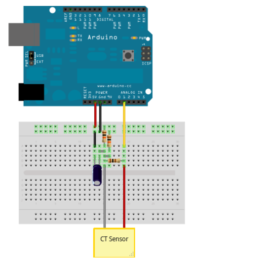
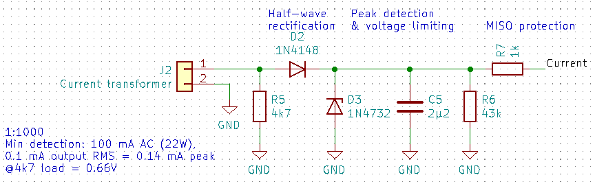
This schematic I've used before and works fine.
Tune R5 for sensitivity, I had a 1:1000 CT.
C5/R6 is the peak detection. Tune to suit your needs.
D3 is for protection.
R7 is for input protection.
Depending on the current the OP wants to sense, R5 may be much too high. CTs can generate rather high voltages on their secondary without a proper "burden". What is the max current to be sensed?
A quick Google search showed me that there are two versions of the sct013, one with voltage output and one with current output. If yours has indeed a voltage output, you can connect it to an analog input and just do an analogRead() to get a reading.
The voltage output being 0-1V, and an absolute value, means you should use the internal 1.1V reference for the ADC. Use
analogReference(INTERNAL);
in your setup() function.
Do some readings to see what value you get when the machine is on. Probably just testing for the reading to be >0 is enough, as with the machine off it should be zero, though I'd prefer to give it a little leeway for interference and consider the machine on when it's greater than say 10, or half of the reading when the machine is running.
Do mind that as it's a rectified AC signal reading the voltage output is likely to be unstable. As the voltage output is 0-1V you can't use a simple peak detection as my circuit, instead take samples for at least 20 ms (or 18 ms if you're on 60 Hz) and take the highest reading from those.
Come to think of it, maybe in my circuit it'd be better to place R5 behind D2 instead, for more accurate readings. But then I was also using it or simple on/of detection.