0.22 is OK but you have to realize that the voltages will be very small, even at 50A the voltage will be only 220mV. Also you need to consider the wire resistance, 22 AWG stranded wire has a resistance of 14.74milliohms/foot, that is a large percentage of the 220milliohm burdon
Are you using a Nano ESP32 as you show in your diagram?
Last time you were using an R4
but you say that i cannot measure 22mV, no i can measure even 1mV because the resolution of my Analog pin is = 3300mV/4096 = 0.805 mV.
I say the problem with 0.2 ohm is with low current consumption it gives a very high current consumption value
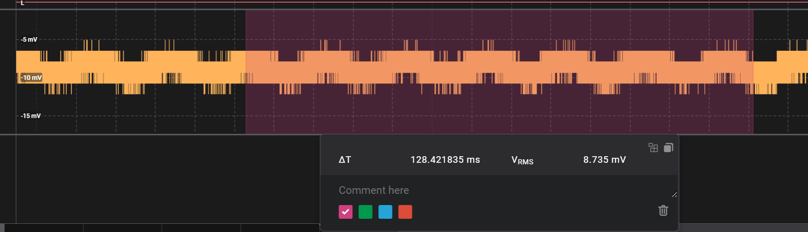
for example i expect 0.137 A from a fan (measured with multimeter), in the oscilloscope i get 8.735 mV on the burden resistor.
which is Iprim = 1.98 A !!!!!!
Hi,
What AC voltage do you measure across the burden resistor with DMM in AC mode?
Thanks.. Tom.. ![]()
![]()
![]()
![]()
Are you using the nano esp32 or the R4?
No AC mode
I'm using arduino nano 33 ble
What are you using to measure your circuit parameters?
Tom.. ![]()
![]()
![]()
![]()
1 Like
The EmonLib is probably not compatible with the nRF52840 processor and may default to 10 bit resolution, so all the calculations will be wrong. The code you show in post #1 will not work as it does not sample correctly. I don't know the accuracy of the nRF52840 ADC but with a 220mV max input it would make sense to use the internal 600mV reference.
In any case, you will have to do calibrations.
Also as I already mentioned, you need to consider wire resistance between the CT and 33BLE otherwise your calculations will be wrong.
Try this program
I think the ACS712 library will work with your setup, if you give it the correct parameters.
Place the burdon resistor right on the CT.
The program will also detect the line frequency.
#include "ACS712.h"

float frequency = 50.0; // 50Hz line frequency
float mVperAmp;

// ACS712(uint8_t analogPin, float volts, uint16_t maxADC, float mVperAmpere)

ACS712 CT(A0, 0.6, 1024, 1);


void setup()
{
  Serial.begin(9600);

  mVperAmp = 0.22 / 50.0; // Burdon resistance / Turns ratio

  analogReadResolution(10);
  analogReference(AR_INTERNAL);

  CT.setNoisemV(0);
  CT.setmVperAmp(mVperAmp);

  unsigned int mp = CT.autoMidPoint();
  Serial.print("MidPoint: ");
  Serial.println(mp);

  Serial.print("mV/A: ");
  Serial.println (CT.getmVperAmp());

  float freqDet = CT.detectFrequency(40.0);
  Serial.print("Frequency: ");
  Serial.println(freqDet);
  Serial.println("--------------------");

}

void loop()
{
  float average = 0;
  uint32_t start = millis();
  for (int i = 0; i < 100; i++)
  {
    average += CT.mA_AC_sampling(frequency, 1);
    // average += ACS.mA_AC();
  }

  float mA = average / 100.0;
  //float duration = (millis() - start) / 1000.0;
  //Serial.print("Time: ");
  //Serial.print(duration);
  Serial.print("Current  mA: ");
  Serial.println(mA);

  delay(3000);
}That should get zero volt from the CT.
Are you using a carbon/film resistor (not wirewound). And short wiring (no aerials).
Did you try moving the CT away from electrical fields, and without a wire through it.
Note that the CT outputs AC, which your analyser might not like.
A scope or DMM set to AC would be better.
Leo..
This topic was automatically closed 180 days after the last reply. New replies are no longer allowed.