The CT I'm using is from Polier. Here is the link to the product. It is a 50:1 transformer, capable of measuring up to 50A. I have chosen a burden resistor of 1 ohm, which is compatible with my calculations.
However, I am facing an issue when trying to measure the current using the EmonLib library, which is also utilized in the example mentioned above. I am uncertain about how to determine the values of the calibration constants: ICAL, VCAL, and PHASECAL.
Before using this library, I attempted to measure the current directly from the analog pin, using the same schematic as in the example but with my specific burden resistor. Unfortunately, the results were inconsistent and yielded unexpected values.
Here's my sketch :
// Pin Definitions
const int analogPin = A0; // Analog input pin connected to the CT circuit

// Constants
const float referenceVoltage = 3.3; // Arduino supply/reference voltage
const int adcResolution = 4096;     // 12-bit ADC resolution
const float burdenResistor = 1; // Burden resistor value in ohms
const float currentTransformerRatio = 50.0; // CT ratio (50:1)
const int numSamples = 1000; // Number of samples for RMS calculation

void setup() {
  Serial.begin(9600);
  analogReadResolution(12);
}

void loop() {
  float voltageSum = 0;

  // Sampling the analog signal
  for (int i = 0; i < numSamples; i++) {
    int analogValue = analogRead(analogPin); // Read the analog value
    float voltage = (analogValue * referenceVoltage) / adcResolution; // Convert ADC value to voltage
    float centeredVoltage = voltage - (referenceVoltage / 2); // Remove the DC offset (biasing)
    voltageSum += centeredVoltage * centeredVoltage; // Sum of squares for RMS calculation
  }

  // Calculate RMS voltage
  float rmsVoltage = sqrt(voltageSum / numSamples);

  // Calculate the current based on the burden resistor and CT ratio
  float current = (rmsVoltage / burdenResistor) * currentTransformerRatio * 1000.0;

  // Print the current value
  Serial.print("Current (A): ");
  Serial.println(current);

  delay(1000); // Delay 1 second between readings
}
Arduino won't measure AC. Beyond a simple current transformer, you need to use a rectifier and capacitor to convert your signal to a representative DC before applying it to A0.
I have tested your code (with some slight modifications) using an Arduino Uno R4 WiFi.
I do not have a current transformer, so I used a function generator to inject a signal into pin A0.
I modified the code as follows:
I removed the '* 1000.0' from the formula for calculating the current (your calculation gives the results in mA, not A).
I altered the reference voltage to match my Arduino Uno R4 reference voltage.
I added lines to turn pin 12 high before the ADC measurements and low again when they were finished, so that I could monitor how long the sampling period was.
#include <digitalWriteFast.h>

// Pin Definitions
const int analogPin = A0; // Analog input pin connected to the CT circuit
const int monitorPin =12; // pin used to monitor ADC convertion time on oscilloscope

// Constants
const float referenceVoltage = 4.694; // Arduino supply/reference voltage
const int adcResolution = 4096;     // 12-bit ADC resolution
const float burdenResistor = 1; // Burden resistor value in ohms
const float currentTransformerRatio = 50.0; // CT ratio (50:1)
const int numSamples = 1000; // Number of samples for RMS calculation

void setup() {
  pinMode(monitorPin, OUTPUT);
  Serial.begin(9600);
  analogReadResolution(12);
}

void loop() {
  float voltageSum = 0;
  digitalWriteFast(monitorPin, HIGH);
  // Sampling the analog signal
  for (int i = 0; i < numSamples; i++) {
    int analogValue = analogRead(analogPin); // Read the analog value
    float voltage = (analogValue * referenceVoltage) / adcResolution; // Convert ADC value to voltage
    float centeredVoltage = voltage - (referenceVoltage / 2); // Remove the DC offset (biasing)
    voltageSum += centeredVoltage * centeredVoltage; // Sum of squares for RMS calculation
  }
  digitalWriteFast(monitorPin, LOW);

  // Calculate RMS voltage
  float rmsVoltage = sqrt(voltageSum / numSamples);

  // Calculate the current based on the burden resistor and CT ratio
  float current = (rmsVoltage / burdenResistor) * currentTransformerRatio;

  // Print the current value
  Serial.print("Current (A): ");
  Serial.println(current);

  delay(1000); // Delay 1 second between readings
}
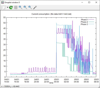
Here are the results, displayed on an oscilloscope and the serial monitor simultaneously.
The yellow trace indicates the width of the sampling period.
The blue trace is a 50Hz sinewave injected into pin A0.
Input amplitude = 1V RMS, to simulate a current of 50A RMS:
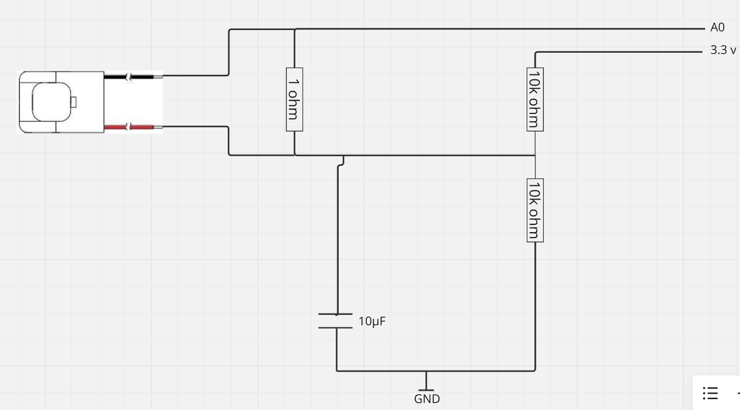
My burden is 1 ohm and two resistor are 10Kohms with a capacitor of 10µF
For the values i tried with an oven to measure its consumption normally i expect 6,51 A but i get 4,7 A or 4 A, and when i don't any device normally i should get 0A or 0.01 for the noise, but i get higher than the expected 0.2 or 0.1 A
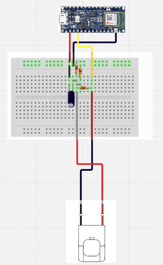
Can you please post a copy of your circuit, a picture of a hand drawn circuit in jpg, png?
Hand drawn and photographed is perfectly acceptable.
Please include ALL hardware, power supplies, component names and pin labels.
Sorry but a Fritzy image is not a schematic, especially f you have to place an addendum about component values.
if your SCT-013 is rated at 50amps it may already have a burden resistor built in
the 100amp SCT-013 sensors I used all have a suitable burden resistor built in - the external circuits just offset the signal for input to the ESP32 ADCs
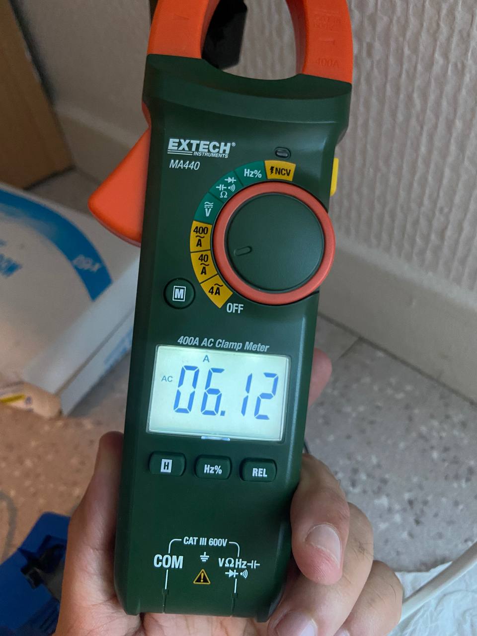
checking the accuracy with a current clamp meter readings are within a few percent
The datasheet for the current transformer doesn't mention a burden resistor.
I think that the fact that the 5A versions use a thicker gauge wire than the 1A versions indicates that the burden resistor is user supplied.
Don't try using the current transformer without a burden resistor - dangerous voltages are generated.
I can confirm that your schematic matches the schematic suggested by openenergymonitor.org, with the caveat that you are using a reference voltage of 3.3V, not 5V.
when i calculate the value of the secondary current with Vmax, I get Isec = Vmax/burden_resistor = 583*10^-3/4.7 = 0.124 A
And Iprimary = Isec * 50 = 0.124 * 50 = 6.20 A (which is the result i expect)
But when i calculate the value of the secondary current with VRMS, i get Isec = Vrms/Burden_resistor = 378.35*10^-3/4.7 = 0.0805 A
And Iprimary = Isec * 50 = 0.0805 * 50 = 4.025 A (which is the result i get in arduino)
So the question here how can i get in the output only the maximum value the wave ?
It is the value my burden resistor, i have changed it.
Now i have found that i measure Vrms not Vmax, so i should multiply by sqrt(2) to obtain the same value as multimeter, but when i do the same thing with the other devices that have a lower current i get value greater than expected