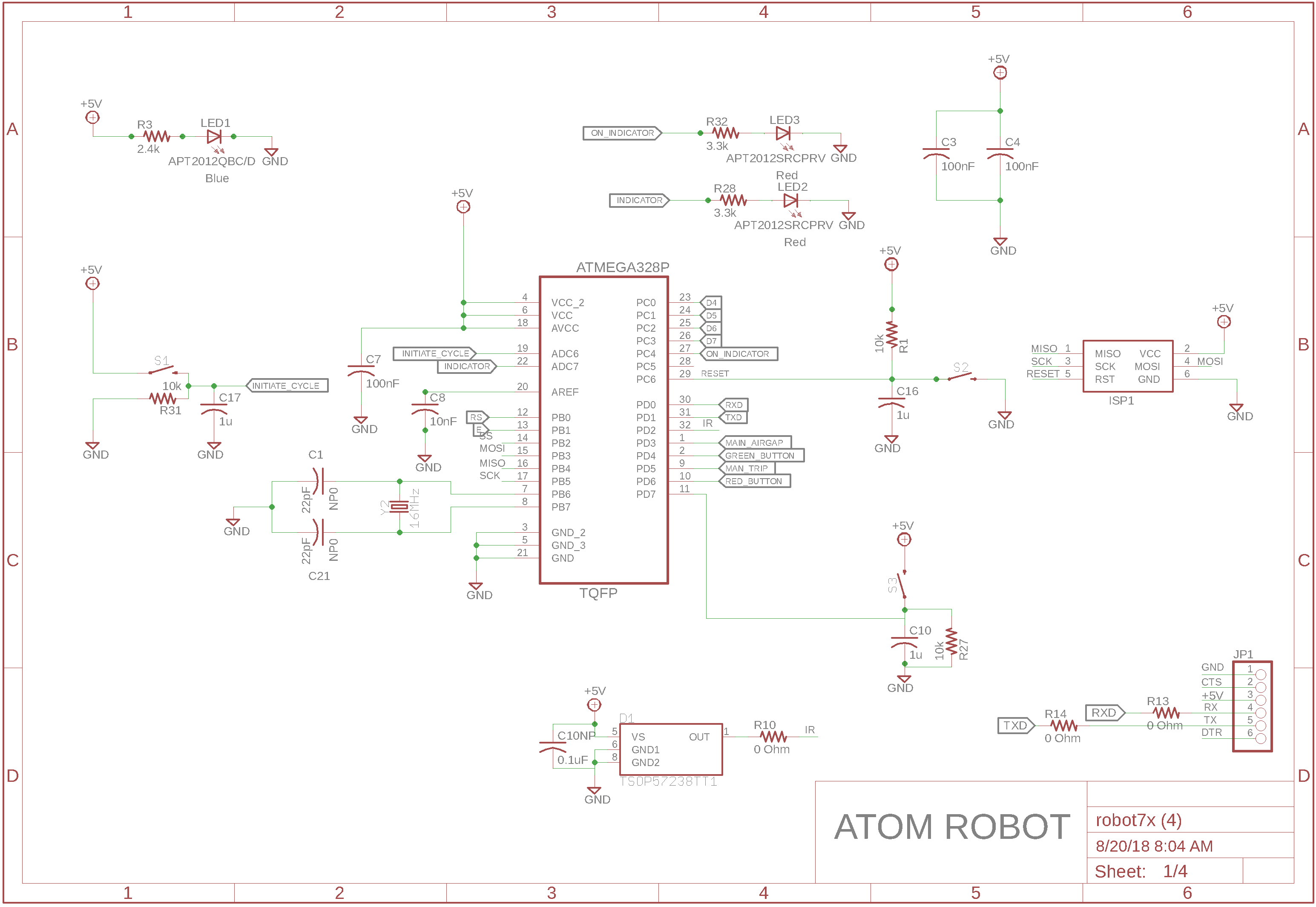
I am trying to program a new custom blank Atmega328p (TQFP 32 pin). I have a custom board spun with this chip. I have all the associated circuitry to get it working, including an external 16MHz crystal , ICSP , reset etc. ( I have attached a snapshot of the schematics below) .
The fundamental problem is that I am unable to flash the chip . The bootloader doesnt seem to flash at all and a regular blink program seems to flash but not work at all (without the bootloader).
I had three approaches after doing some deep research .
I was able to read the fuses from the blank chip using avrdude and a usbtiny programmer. This was Lfuse : 0x62, Hfuse: 0xD9, Efuse: 0x07. I tried setting the fuses to match an arduino UNO that i have, which is Lfuse : 0xFF, Hfuse: 0xDE, Efuse: 0x05. As soon as i do this, I get a dreader error all the time after that , which is the following:
.....
"Initialization failed, rc=1"
I tried to flash the bootloader directly using the arduino IDE, but the same error shows up. ( This is probably of the fuses set by the arduino UNO's bootloader which are the same as above.
I tried flashing just a regular example blink led code. This seems to upload but doesnt run, as we dont see any pin toggle on the chip, using an oscilloscope.
I have already bricked 5 boards and i really need to get this up and running asap. Im trying to even figure out if its the fuses or any hardware issue. I checked all the individual pins of the chip and everything seems to be normal and compare with the arduino UNO's pins.
Please give your suggestions on what could be a solution and also how to recover the bricked boards!!
You could not test the full circuit with a 328P DIP as that is missing ADC6 and ADC7 (A6 and A7) which are two analogue only pins on the SMD chip that you appear to be using as digital.
The serial program connection does not look right either, DTR does not appear connected, there is normally a capacitor between that and the processor RESET line.
When you use ArduinoISP to write a bootloader, you must provide a board selection with exactly
matching signature bytes to the hardware of the chip - so you may have to create a new boards.txt
entry just to do this if the chip isn't standard (every part number has different signture bytes, and
sometimes different fuse bit settings - for instance some 328's expect undefined fuse bits to be 1's
and others don't.
So off to the datasheet and write down all these details for the exact part number of the TQFN part
you have.
Then check in the AVR include files what device name is needed to match that,
Then see if one of the existing boards.txt entries matches in all particulars - if not clone a new
entry with everything matching the hardware.
Then you should be able to flash a bootloader with that setting (if using ArduinoISP).
At least any error messages from avrdude should make sense now...
Having flashed the bootloader the "signature bytes" seen in subsequent sketch uploads are actually
a property of the bootloader you used, not the hardware - you can make every 328 pretend to be an
Uno because of this (if you used the optiboot or later bootloaders I think).
Also note that some versions of the Arduino software have a broken ArduinoISP sketch in them (or
perhaps I broke mine!)
srnet:
You could not test the full circuit with a 328P DIP as that is missing ADC6 and ADC7 (A6 and A7) which are two analogue only pins on the SMD chip that you appear to be using as digital.
Indeed ADC6 and ADC7 only go the ADC multiplexer, and are ADC inputs only, you can't power an LED from them.
The serial program connection does not look right either, DTR does not appear connected, there is normally a capacitor between that and the processor RESET line.
Lose the capacitor on the reset pin, add a diode between it and DTR, cathode to DTR. Works for me, doesn't
cause damage to the reset pin's protection diode either.
BTW if you plan to use a lot of TQFN parts its worth getting a ZIF socket for TQFN32's so you can
ArduinoISP program bootloaders in bulk and have a stock of them on hand - saves having to worry
about this for every project individually.
You'll need a 16MHz crystal and caps to go with the ZIP socket - I found a programming board for some
other microcontroller and rewired its pcb to do this.
Another approach might be using a TQFN breakout board with a clothespeg or something to press
each device down to the pads during programming - the leads stick out slightly below the package if
you've handled them carefully so there should be enough spring pressure in every leg to make contact
OK.
While trying out various things since morning, I have come to a conclusion that it's because of the external oscillator. Tell me if this makes sense,
I tried flashing the bootloader with the boards.txt changed to the fuse values of the default chip (With the Internal Oscillator). And it worked!
I even uploaded code on the chip through the programmer and it worked as expected. (Toggled a few gpios)
All the 5 bricked boards had the fuses for the chip to work with the external oscillator. So I have come to a conclusion that this is a clock problem.
However, I can definitely see the 16MHz signal on the XTAL1 & XTAL2 pins (The fuses are set to Low power Crystal Oscillator mode with lfuse 0xFF matching the UNO). Any ideas now with this information?
I'm convinced it's not a software issue now as this works perfectly fine with the internal and also because I'm using the correct fuse values.