I'm working on a CAN project and I wanted to ask about a strange issue I'm encountering.
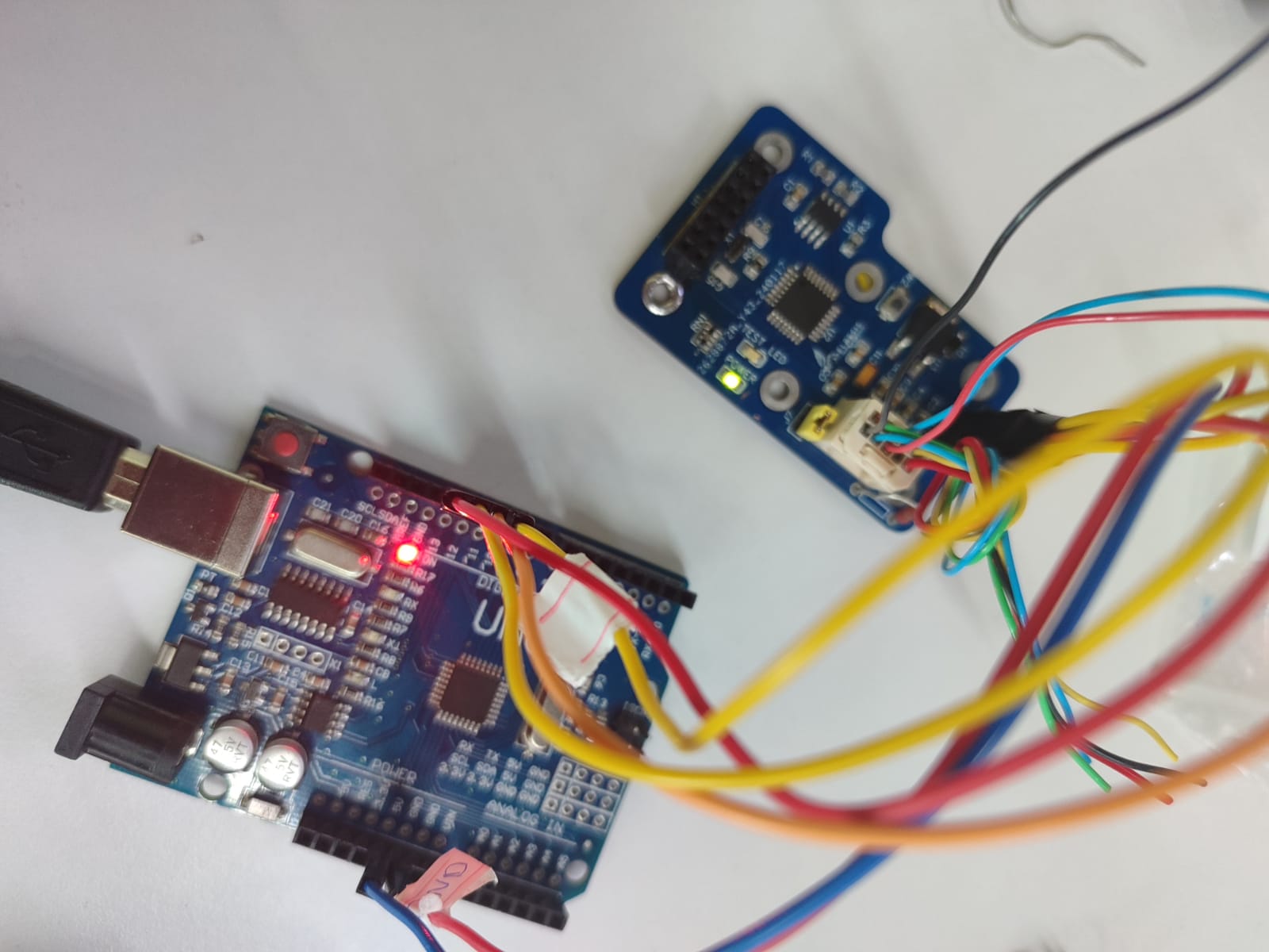
I’m using a PEAK-System USB-CAN interface to send CAN messages. The CAN_H and CAN_L lines from this USB device are connected to a custom module that includes an MCP2515 and an ATmega328, which is also connected to an Arduino Uno. On top of this module, I’ve connected a display to shoÖnceden biçimlendirilmiş metinw received CAN data.
The goal is to receive CAN messages via the MCP2515 and display them using Arduino.
The issue is: when the USB-CAN interface is not connected to the module (i.e., when there's physically no CAN connection), the Arduino still behaves like it’s receiving CAN messages. It shows CAN_MSGAVAIL, and I get seemingly random two frames of data.
I suspect these could be caused by noise on the bus, and I can work on filtering or shielding. But what I don’t understand is why the MCP2515 thinks it's connected to a valid CAN bus even when there's clearly no transmitter or proper CAN activity.
Could this behavior be caused by defining the CS pin as 10 in my code? Or could there be a hardware-related issue on the board or the module itself?
Any thoughts or suggestions would be appreciated!
#include <SPI.h>
#include <mcp_can.h>

const int SPI_CS_PIN = 10;
MCP_CAN CAN(SPI_CS_PIN); // MCP2515 modülü CS pini

void setup() {
  Serial.begin(115200);
  delay(500);
  Serial.println("Başlatılıyor...");

  // CAN başlatma denemesi
  while (CAN_OK != CAN.begin(MCP_ANY, CAN_500KBPS, MCP_8MHZ)) {
    Serial.println("CAN BUS init failed, retrying...");
    delay(500);
  }
  Serial.println("CAN BUS init OK!");

  // Maske ve filtre (sadece belirli ID'yi dinle)
  CAN.init_Mask(0, true, 0x1FFFFFFF);
  CAN.init_Filt(0, true, 0x18F00400);

  // Listen-only mode
  CAN.setMode(MCP_LISTENONLY);
}

void loop() {
  byte check = CAN.checkReceive();

  Serial.print("checkReceive() = ");
  Serial.println(check);

  if (check == CAN_MSGAVAIL) {
    long unsigned int rxId;
    unsigned char len = 0;
    unsigned char buf[8];

    CAN.readMsgBuf(&rxId, &len, buf);

    Serial.print("ID: 0x");
    Serial.print(rxId, HEX);
    Serial.print("  Data: ");
    for (int i = 0; i < len; i++) {
      Serial.print(buf[i], HEX);
      Serial.print(" ");
    }
    Serial.println();
  }

  delay(500);
}
Post an annotated schematic showing exactly how you have wired it and are powering it. Show all power sources. Hopefully the bus is at least 1 meter long.
I moved your topic to an appropriate forum category @bucketposyy.
In the future, when creating a topic please take some time to pick the forum category that best suits the subject of your topic. There is an "About the _____ category" topic at the top of each category that explains its purpose.
Unfortunately, I'm unable to share a schematic of the module I’m currently working with, as it is a custom-designed board developed in-house for a proprietary project at the company I’m employed with. Due to confidentiality constraints, disclosing specific design details is not permitted.
However, I have tested the same setup by replacing the custom board with a standard MCP2515 module, and the code runs flawlessly in that configuration. This leads me to believe that the issue lies within the hardware implementation of the custom module rather than the software or firmware.
Given that, I would appreciate any insights or recommendations on key hardware-level factors I should verify or troubleshoot in a custom MCP2515-based CAN module, particularly regarding:
Proper decoupling and power supply filtering
Crystal oscillator specification and placement
SPI line layout and signal integrity
Termination resistor placement and value
Common design pitfalls you may have encountered in similar custom implementations
Your guidance would be greatly appreciated. Thank you in advance for your support.
Is the MCP2515 chip on the reverse side of the custom board? If so, it sounds like your Uno is joined to the SPI bus on the custom board and therefore it sees the SPI traffic between the onboard Atmega328 and the MCP2515. No easy fix as you either need to cut tracks on the custom board to disconnect the Atmega328 or change its firmware.
Currently you have two microcontrollers trying to be SPI masters and no way of coordinating their activity so they both are attempting to talk to the MCP2515 at the same time.
Are you trying to diagnose problems with the custom board?
If your company didn't design it then why are you messing with it? If you have been asked to analyse the SPI data then use a proper SPI analyzer tool.
That narrows this down to a guessing game. If you do not have a scope, logic analyzer and a CAN analyzer I recommend you get one of each. The only other suggestion is to slow the CAN bus down until it is working.
Yes, the chip is on the back side. The module was designed by our company. What I'm trying to do is a motor runtime counter for a marine engine. They designed this custom board to make the connections easier.
However, I'm currently experiencing the same issue even when I replace the custom board with a standard MCP2515 module. I initially thought it was a connection problem caused by jumper wires, but even if that's the case, it doesn't really explain why the system behaves like it's connected even when the CAN bus isn't active.
For example, I can get this output even when no USB CAN device is plugged in:
if you are going to work on interfacing sensors etc to microcontrollers it is worth while getting basic knowledge and use of oscilloscopes and logic analyzers
quite often a problem is not with the program but the device connections etc and an oscilloscope or logic analyzer will help solving the problem