Datalogging 6 analog inputs with Uno...

Hi,
Usually on EEVblog, but now I've got to program 2 Arduinos as part of my final project!
I'm studying to be an Engineering Watch officer, so we don't do much "small" electronics and no microcontroller programming, thusly, I'm self taught...
The 4 load cell amplifier took me ages to get from concept to working well.
I don't expect anyone to do my work for me, but pointing out mistakes or impossible/stupid stuff is much appreciated.
If I'm doing something that already exists and just needs #define renaming (etc), please point it out, it will give me more time to refine the data processing.

The Arduino is a standard Uno V3
Uno
Upon it is mounted an Adafruit data-logger
Adafruit Datalogger
This will use only the 6 analogue pins to make "relative" measurements.
These 6 pin are distributed as such:
1 for the temperature sensor, TMP 36 with the on board 5V.
TMP 36
1 For the wind speed sensor; a DIY anemometer that registers 0 to 3.3V.
Anenometer log
4 that are connector to 4 load cells, with a DIY analogue amplifier.
The signal with no force is 1.5V, the max is 3V, the min is 0V.
Analogue Amplifier
This has been converted into a PCB and bodged to spec.
Finalising PCB
All is supplied with a single 12V/0.9A powers supply.
The ground is common amongst all the parts.

I will be using the Adafruit example as inspiration for the code.
Datalogger original code
But my version will use mains power as the load cells in continuous usage burn about 80mA, for a total of about 200mA.
(I've got some ideas on power optimisation, but I'll need to spin a new board for that)

Sequence that I'm trying to code:

Read clock, save result as RTC
Read pin 0 1times over 1mS, save results as TMP.
Delay 4mS
Read pin 1 10times over 10mS, save results as WDS.
Delay 5mS
Read pin 2 5times over 5mS, save results as LC1.
Delay 5mS
Read pin 3 5times over 5mS, save results as LC2.
Delay 5mS
Read pin 4 5times over 5mS, save results as LC3.
Delay 5mS
Read pin 5 5times over 5mS, save results as LC4.
Delay 4930ms
Start loop again

Below is the code, I'm writing it right now, so it's a "work in progress"...

sketch_memoire01.ino (2.37 KB)

I think I've mostly done it... Just a couple of points I need to clear up:

int wdsReading = analogRead(wdsPin);
 delay(10);
  int tmpReading = analogRead(tmpPin);  
 delay(10);
   // converting that reading to voltage, for 3.3v arduino use 3.3
  float voltage = tmpReading * 3.3 / 1024;  
  float temperatureC = (voltage - 0.5) * 100 ;

  int lc1Reading = analogRead(lc1Pin);
 delay(5);           // Short delay, buffered signal to ground via 10k resistor.
  int lc2Reading = analogRead(lc2Pin);
 delay(5);           // Short delay, buffered signal to ground via 10k resistor.
  int lc3Reading = analogRead(lc3Pin);
 delay(5);           // Short delay, buffered signal to ground via 10k resistor.
   int lc4Reading = analogRead(lc4Pin);
 delay(5);           // Short delay, buffered signal to ground via 10k resistor.
      
 
  logfile.print(", ");    
  logfile.print(wdsReading);
  logfile.print(", ");    
  logfile.println(temperatureC);
  logfile.print(", ");    
  logfile.print(lc1Reading);
  logfile.print(", ");    
  logfile.print(lc2Reading);
  logfile.print(", ");    
  logfile.print(lc3Reading);
  logfile.print(", ");    
  logfile.print(lc4Reading);        
#if ECHO_TO_SERIAL
  Serial.print(", ");   
  Serial.print(wdsReading);
  Serial.print(", ");    
  Serial.println(temperatureC);
  Serial.print(", ");   
  Serial.print(lc1Reading);
  Serial.print(", ");   
  Serial.print(lc2Reading);
  Serial.print(", ");   
  Serial.print(lc3Reading);
  Serial.print(", ");   
  Serial.print(lc4Reading);
#endif //ECHO_TO_SERIAL

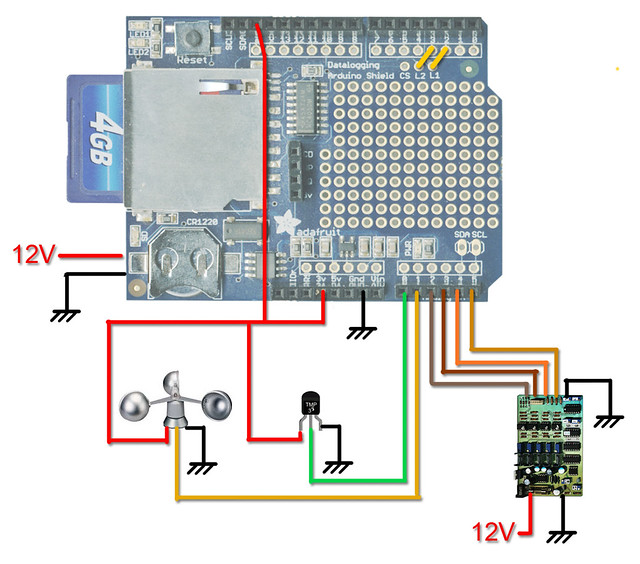
The WDS is a anemometer, based on a tiny DC motor whose voltage signal is smoothed by a capacitor, how would one go about averaging 5 or 10 measurements over 100 or 200mS?
Same goes for the "lc", these load cells have a bit of noise in the 1 to 2MHz range (due to ringing caused by a ICL negative voltage pump), so an average over 5mS would improve precision by 5% to 10%.
If I could do a board re-spin, I would "program with solder" my negative power rail in a totally different manner... But now I have to deal with a 20mV, 1.25Mhz "spike" that I can't filter more than what I've already filtered it.
But it this "spike" gets in the Op Amps via their supply pins and the resulting sine gets amplified in the second amplification stage.

The full code:

#include <SD.h>
#include <Wire.h>
#include <RTClib.h>

/* Memoire sketch01
 */

#define aref_voltage 3.3   // 3.3V is the ref voltage
#define LOG_INTERVAL  5000 // mills between entries (5s)
#define ECHO_TO_SERIAL   1 // echo data to serial port
#define WAIT_TO_START    0 // Wait for serial input in setup()

// the digital pins that connect to the LEDs
#define redLEDpin 3
#define greenLEDpin 4

// The analog pins that connect to the sensors
#define wdsPin 0           // analog 0
#define tmpPin 1           // analog 1
#define lc1Pin 2           // analog 2
#define lc2Pin 3           // analog 3
#define lc3Pin 4           // analog 4
#define lc4Pin 4           // analog 5


RTC_DS1307 RTC; // define the Real Time Clock object

// for the data logging shield, we use digital pin 10 for the SD cs line
const int chipSelect = 10;

// the logging file
File logfile;

void error(char *str)
{
  Serial.print("error: ");
  Serial.println(str);
  
  // red LED indicates error
  digitalWrite(redLEDpin, HIGH);
  
  while(1);
}

void setup(void)
{
  Serial.begin(9600);
  Serial.println();
  
#if WAIT_TO_START
  Serial.println("0"); //automatic start, no need to type in anything.
  while (!Serial.available());
#endif //WAIT_TO_START

  // initialize the SD card
  Serial.print("Initializing SD card...");
  // make sure that the default chip select pin is set to
  // output, even if you don't use it:
  pinMode(10, OUTPUT);
  
  // see if the card is present and can be initialized:
  if (!SD.begin(chipSelect)) {
    Serial.println("Card failed, or not present");
    // don't do anything more:
    return;
  }
  Serial.println("card initialized.");
  
  // create a new file
  char filename[] = "CUBE1.CSV";
  for (uint8_t i = 0; i < 100; i++) {
    filename[6] = i/10 + '0';
    filename[7] = i%10 + '0';
    if (! SD.exists(filename)) {
      // only open a new file if it doesn't exist
      logfile = SD.open(filename, FILE_WRITE); 
      break;  // leave the loop!
    }
  }
  
  if (! logfile) {
    error("couldnt create file");
  }
  
  Serial.print("Logging to: ");
  Serial.println(filename);

  Wire.begin();  
  if (!RTC.begin()) {
    logfile.println("RTC failed");
#if ECHO_TO_SERIAL
    Serial.println("RTC failed");
#endif  //ECHO_TO_SERIAL
  }
  

  logfile.println("millis,time,temp,speed,sensor1,sensor2,sensor3,sensor");    
#if ECHO_TO_SERIAL
  Serial.println("millis,time,temp,speed,sensor1,sensor2,sensor3,sensor");
#if ECHO_TO_SERIAL// attempt to write out the header to the file
  if (logfile.writeError || !logfile.sync()) {
    error("write header");
  }
  
  pinMode(redLEDpin, OUTPUT);
  pinMode(greenLEDpin, OUTPUT);
 
   // If you want to set the aref to something other than 5v
  //analogReference(EXTERNAL);
}

void loop(void)
{
  DateTime now;

  // delay for the amount of time we want between readings
  delay((LOG_INTERVAL -1) - (millis() % LOG_INTERVAL));
  
  digitalWrite(greenLEDpin, HIGH);

  // log milliseconds since starting
  uint32_t m = millis();
  logfile.print(m);           // milliseconds since start
  logfile.print(", ");    
#if ECHO_TO_SERIAL
  Serial.print(m);         // milliseconds since start
  Serial.print(", ");  
#endif

  // fetch the time
  now = RTC.now();
  // log time
  logfile.print(now.get()); // seconds since 2000
  logfile.print(", ");
  logfile.print(now.year(), DEC);
  logfile.print("/");
  logfile.print(now.month(), DEC);
  logfile.print("/");
  logfile.print(now.day(), DEC);
  logfile.print(" ");
  logfile.print(now.hour(), DEC);
  logfile.print(":");
  logfile.print(now.minute(), DEC);
  logfile.print(":");
  logfile.print(now.second(), DEC);
#if ECHO_TO_SERIAL
  Serial.print(now.get()); // seconds since 2000
  Serial.print(", ");
  Serial.print(now.year(), DEC);
  Serial.print("/");
  Serial.print(now.month(), DEC);
  Serial.print("/");
  Serial.print(now.day(), DEC);
  Serial.print(" ");
  Serial.print(now.hour(), DEC);
  Serial.print(":");
  Serial.print(now.minute(), DEC);
  Serial.print(":");
  Serial.print(now.second(), DEC);
#endif //ECHO_TO_SERIAL


  int wdsReading = analogRead(wdsPin);
 delay(10);
  int tmpReading = analogRead(tmpPin);  
 delay(10);
   // converting that reading to voltage, for 3.3v arduino use 3.3
  float voltage = tmpReading * 3.3 / 1024;  
  float temperatureC = (voltage - 0.5) * 100 ;

  int lc1Reading = analogRead(lc1Pin);
 delay(5);           // Short delay, buffered signal to ground via 10k resistor.
  int lc2Reading = analogRead(lc2Pin);
 delay(5);           // Short delay, buffered signal to ground via 10k resistor.
  int lc3Reading = analogRead(lc3Pin);
 delay(5);           // Short delay, buffered signal to ground via 10k resistor.
   int lc4Reading = analogRead(lc4Pin);
 delay(5);           // Short delay, buffered signal to ground via 10k resistor.
      
 
  logfile.print(", ");    
  logfile.print(wdsReading);
  logfile.print(", ");    
  logfile.println(temperatureC);
  logfile.print(", ");    
  logfile.print(lc1Reading);
  logfile.print(", ");    
  logfile.print(lc2Reading);
  logfile.print(", ");    
  logfile.print(lc3Reading);
  logfile.print(", ");    
  logfile.print(lc4Reading);        
#if ECHO_TO_SERIAL
  Serial.print(", ");   
  Serial.print(wdsReading);
  Serial.print(", ");    
  Serial.println(temperatureC);
  Serial.print(", ");   
  Serial.print(lc1Reading);
  Serial.print(", ");   
  Serial.print(lc2Reading);
  Serial.print(", ");   
  Serial.print(lc3Reading);
  Serial.print(", ");   
  Serial.print(lc4Reading);
#endif //ECHO_TO_SERIAL

  digitalWrite(greenLEDpin, LOW);
}

Trying to integrate this code into mine:

For your average you might want to use what is called "olympic averaging" - see the second post in THIS thread for an example (they often use that method over in the PIC processor forums). It works pretty well to keep the garbage from affecting the reading.

gpsmikey:
For your average you might want to use what is called "olympic averaging" - see the second post in THIS thread for an example (they often use that method over in the PIC processor forums). It works pretty well to keep the garbage from affecting the reading.

Thanks will do...

But right now, I'm back to square one...
I'm probably missing something basic/silly.
I am using 2 Adafruit datalogging shields to log 2 sets of 4 independent load cells and I'm stumbling at the last hurdle...
The Aduinos Uno are stock, no jumpers.

When all the cells are plugged in, the shields lock up when the green LED is lit (that's during the write stage of the loop).

The load cell circuit emits 1.5V with no load. A positive load makes them go towards 0, negative load makes them go toward 3.3V.

The code I am using is based on the one provided by Adafruit, simply modded for the 6 analogue signals:

#include <SD.h>
#include <Wire.h>
#include "RTClib.h"

// A simple data logger for the Arduino analogue pins

// how many milliseconds between grabbing data and logging it. 1000 ms is once a second
#define LOG_INTERVAL  1000 // mills between entries (reduce to take more/faster data)

// how many milliseconds before writing the logged data permanently to disk
// set it to the LOG_INTERVAL to write each time (safest)
// set it to 10*LOG_INTERVAL to write all data every 10 datareads, you could lose up to 
// the last 10 reads if power is lost but it uses less power and is much faster!
#define SYNC_INTERVAL 1000 // mills between calls to flush() - to write data to the card
uint32_t syncTime = 0; // time of last sync()

#define ECHO_TO_SERIAL   1 // echo data to serial port
#define WAIT_TO_START    0 // Wait for serial input in setup()

// the digital pins that connect to the LEDs
#define redLEDpin 2
#define greenLEDpin 3

// The analog pins that connect to the sensors
#define tempPin 0                // analog 0
#define windPin 1                // analog 1
#define cube2Pin 2               // analog 2
#define cube3Pin 3               // analog 3
#define cube4Pin 4               // analog 4
#define cube5Pin 5               // analog 5
#define BANDGAPREF 14            // special indicator that we want to measure the bandgap

#define aref_voltage 3.3         // we tie 3.3V to ARef and measure it with a multimeter!
#define bandgap_voltage 1.1      // this is not super guaranteed but its not -too- off

RTC_DS1307 RTC; // define the Real Time Clock object

// for the data logging shield, we use digital pin 10 for the SD cs line
const int chipSelect = 10;

// the logging file
File logfile;

void error(char *str)
{
  Serial.print("error: ");
  Serial.println(str);
  
  // red LED indicates error
  digitalWrite(redLEDpin, HIGH);

  while(1);
}

void setup(void)
{
  Serial.begin(9600);
  Serial.println();
  
  // use debugging LEDs
  pinMode(redLEDpin, OUTPUT);
  pinMode(greenLEDpin, OUTPUT);
  
#if WAIT_TO_START
  Serial.println("Type any character to start");
  while (!Serial.available());
#endif //WAIT_TO_START

  // initialize the SD card
  Serial.print("Initializing SD card...");
  // make sure that the default chip select pin is set to
  // output, even if you don't use it:
  pinMode(10, OUTPUT);
  
  // see if the card is present and can be initialized:
  if (!SD.begin(chipSelect)) {
    error("Card failed, or not present");
  }
  Serial.println("card initialized.");
  
  // create a new file
  char filename[] = "LOGGER00.CSV";
  for (uint8_t i = 0; i < 100; i++) {
    filename[6] = i/10 + '0';
    filename[7] = i%10 + '0';
    if (! SD.exists(filename)) {
      // only open a new file if it doesn't exist
      logfile = SD.open(filename, FILE_WRITE); 
      break;  // leave the loop!
    }
  }
  
  if (! logfile) {
    error("couldnt create file");
  }
  
  Serial.print("Logging to: ");
  Serial.println(filename);

  // connect to RTC
  Wire.begin();  
  if (!RTC.begin()) {
    logfile.println("RTC failed");
#if ECHO_TO_SERIAL
    Serial.println("RTC failed");
#endif  //ECHO_TO_SERIAL
  }
  

  logfile.println("millis,stamp,datetime,temp,wind,cube2,cube3,cube4,cube5,vcc");    
#if ECHO_TO_SERIAL
  Serial.println("millis,stamp,datetime,temp,wind,cube2,cube3,cube4,cube5,vcc");
#endif //ECHO_TO_SERIAL
 
  // If you want to set the aref to something other than 5v
  analogReference(EXTERNAL);
}

void loop(void)
{
  DateTime now;

  // delay for the amount of time we want between readings
  delay((LOG_INTERVAL -1) - (millis() % LOG_INTERVAL));
  
  digitalWrite(greenLEDpin, HIGH);
  
  // log milliseconds since starting
  uint32_t m = millis();
  logfile.print(m);           // milliseconds since start
  logfile.print(", ");    
#if ECHO_TO_SERIAL
  Serial.print(m);         // milliseconds since start
  Serial.print(", ");  
#endif

  // fetch the time
  now = RTC.now();
  // log time
  logfile.print(now.unixtime()); // seconds since 1/1/1970
  logfile.print(", ");
  logfile.print('"');
  logfile.print(now.year(), DEC);
  logfile.print("/");
  logfile.print(now.month(), DEC);
  logfile.print("/");
  logfile.print(now.day(), DEC);
  logfile.print(" ");
  logfile.print(now.hour(), DEC);
  logfile.print(":");
  logfile.print(now.minute(), DEC);
  logfile.print(":");
  logfile.print(now.second(), DEC);
  logfile.print('"');
#if ECHO_TO_SERIAL
  Serial.print(now.unixtime()); // seconds since 1/1/1970
  Serial.print(", ");
  Serial.print('"');
  Serial.print(now.year(), DEC);
  Serial.print("/");
  Serial.print(now.month(), DEC);
  Serial.print("/");
  Serial.print(now.day(), DEC);
  Serial.print(" ");
  Serial.print(now.hour(), DEC);
  Serial.print(":");
  Serial.print(now.minute(), DEC);
  Serial.print(":");
  Serial.print(now.second(), DEC);
  Serial.print('"');
#endif //ECHO_TO_SERIAL

  analogRead(tempPin);
  delay(10); 
  int tempReading = analogRead(tempPin);  
  
  analogRead(windPin); 
  delay(10);
  int windReading = analogRead(windPin);    

  analogRead(cube2Pin); 
  delay(10);
  int cube2Reading = analogRead(cube2Pin);    

  analogRead(cube3Pin); 
  delay(10);
  int cube3Reading = analogRead(cube3Pin);   

  analogRead(cube4Pin); 
  delay(10);
  int cube4Reading = analogRead(cube4Pin);
  
  analogRead(cube5Pin); 
  delay(10);
  int cube5Reading = analogRead(cube5Pin);  
  
  // ADC temp reading to centigrade
  float voltage0 = tempReading * 3.3 / 1024;  
  float temperatureC = (voltage0 - 0.5) * 100 ;
  
  logfile.print(", ");    
  logfile.print(temperatureC);
  logfile.print(", ");    
  logfile.print(windReading);
  logfile.print(", ");    
  logfile.print(cube2Reading);
  logfile.print(", ");    
  logfile.print(cube3Reading);
  logfile.print(", ");    
  logfile.print(cube4Reading);
  logfile.print(", ");    
  logfile.print(cube5Reading);     
#if ECHO_TO_SERIAL
  Serial.print(", ");   
  Serial.print(temperatureC);
  Serial.print(", ");    
  Serial.print(windReading);
  Serial.print(", ");    
  Serial.print(cube2Reading);
  Serial.print(", ");    
  Serial.print(cube3Reading);
  Serial.print(", ");    
  Serial.print(cube4Reading);
  Serial.print(", ");    
  Serial.print(cube5Reading);
#endif //ECHO_TO_SERIAL

  // Log the estimated 'VCC' voltage by measuring the internal 1.1v ref
  analogRead(BANDGAPREF); 
  delay(10);
  int refReading = analogRead(BANDGAPREF); 
  float supplyvoltage = (bandgap_voltage * 1024) / refReading; 
  
  logfile.print(", ");
  logfile.print(supplyvoltage);
#if ECHO_TO_SERIAL
  Serial.print(", ");   
  Serial.print(supplyvoltage);
#endif // ECHO_TO_SERIAL

  logfile.println();
#if ECHO_TO_SERIAL
  Serial.println();
#endif // ECHO_TO_SERIAL

  digitalWrite(greenLEDpin, LOW);

  // Now we write data to disk! Don't sync too often - requires 2048 bytes of I/O to SD card
  // which uses a bunch of power and takes time
  if ((millis() - syncTime) < SYNC_INTERVAL) return;
  syncTime = millis();
  
  // blink LED to show we are syncing data to the card & updating FAT!
  digitalWrite(redLEDpin, HIGH);
  logfile.flush();
  digitalWrite(redLEDpin, LOW);
  
}

Without the cells plugged in, and/or the signal cable between the shield and the load cells not plugged in, the shield works...
I don't know if the problem is code, Arduino or having to buffer the signal...

Any help/pointers would be greatly appreciated.

I don't see how your code is using two SD cards. It only contains one instance of the SD class. If you've got two cards plugged in, they will fight each other.

If you do have two SD card shields, then you need separate CS pins for them. (Card Select or Chip Select.)

Two shields will also have two RTC clocks. They need to have different addresses or they will also fight.

It's two separate systems, each with an unique SD card and clock.
The only thing they share is the mains.

I've tested the pins:

3V+ on the 4 cells pins with NO supply and connected.

4.2V on the 4 cells pins with supply and connected (max read out of the ADC)

1.15Von the 4 cells pins with NO supply and NOT connected ????

I put an opamp buffer between the source the shield...

It does not hang up any more, but acts weird...
When I reset the shield:

  • On the shield side of the buffer: 3.65V
  • On the amplifier side 1.3V (Ok).
    It's like the arduino is trying to push a charge back across the buffer and hitting it's +VCC
    ADC's are not meant to do that!

Can't add picture, security check does not like a messy desk!

Edit:
Getting better. Using the shield's 3V has helped.
But the voltage still sometimes shoots up to 3.6V on pin2.

Signal "cube3" is what I expect;

datetime temp wind cube2 cube3 cube4 cube5
"2016/5/1 21:42:3" 20.9 410 1023 404 1023 1023
"2165/165/165 165:165:85" 20.9 335 342 468 1023 1023
"2016/5/1 21:42:5" 20.9 392 1023 428 1023 1023
"2165/165/165 165:165:85" 20.9 305 354 475 1023 1023
"2165/165/165 165:165:85" 20.9 401 1023 475 1023 1023
"2016/5/1 21:42:8" 20.9 265 186 396 647 1023
"2016/5/1 21:42:9" 20.9 301 190 405 656 1023
"2016/5/1 21:42:10" 20.9 328 198 408 657 1023
"2016/5/1 21:42:11" 20.9 292 203 412 663 1023
"2016/5/1 21:42:12" 20.9 294 205 413 666 1023
"2016/5/1 21:42:13" 20.9 293 210 418 673 1023
"2016/5/1 21:42:14" 20.9 292 213 423 673 1023
"2016/5/1 21:42:34" 20.9 424 1023 518 856 1023
"2165/5/1 21:42:35" 20.9 392 1023 542 1023 1023

It seems I have to do physical mod on the board to have access to the two pin...
The RTC's I2C bus uses pin a4 and a5... These need to be moved to a software based I2C solution.
https://forums.adafruit.com/viewtopic.php?f=31&t=45413
However, despite there being various explanation on "how to do it", none are 100% clear and none include a "step by step".

... But on the good side, all my analogue stuff works, phew!

Giving up...
The UNO's vaunted 6 analogue inputs are pure "marketing" bull and I can't do anything about it.
Luckily my sensors are "push pull" so I can interpolate from two in a cross.
But I lose the averaging out and some data quality of having 4.

Pissed off at having been "marketed" at by Arduino and Adafruit.
It's duckling stupid, I would have simple gone the MEGA or MINI route from the start had they not "marketed".

No sure I'll do another project with Arduino, PI seems less "marketing" for sensor projects.