Hi!
My project is to make a two quadrant DC/DC converter. For now, I am just trying to make the buck converter functionality work.
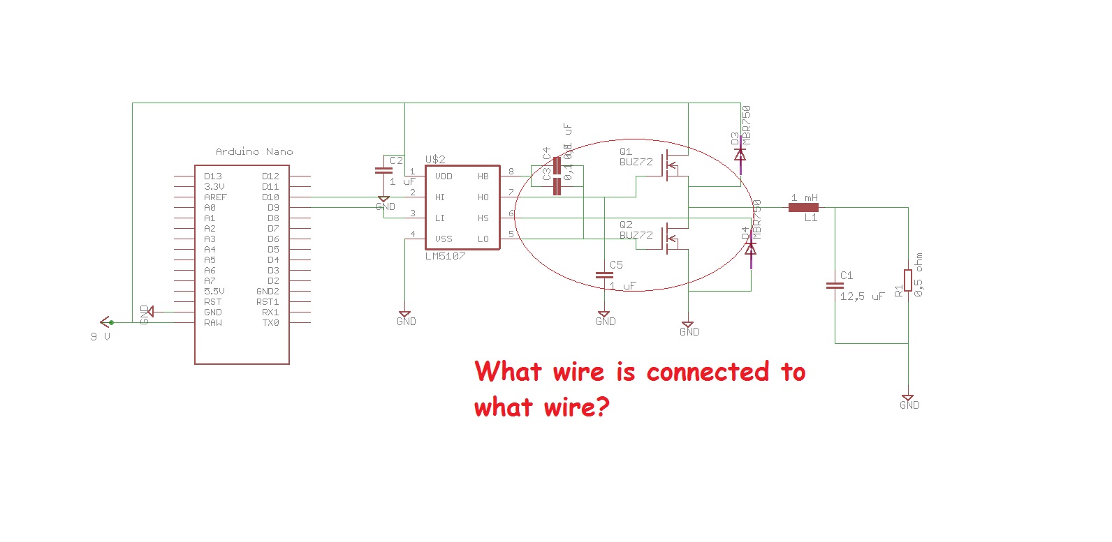
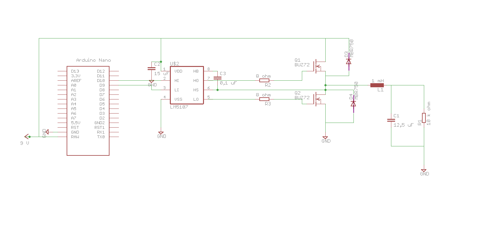
Circuit:
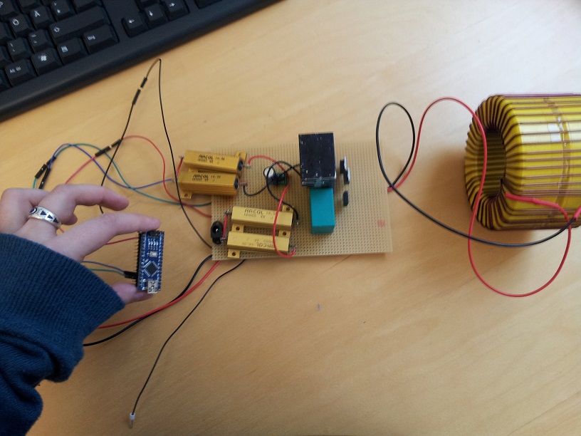
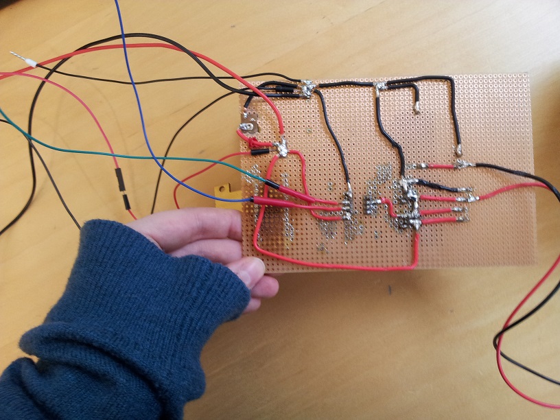
My circuit wiring is attached to the post.
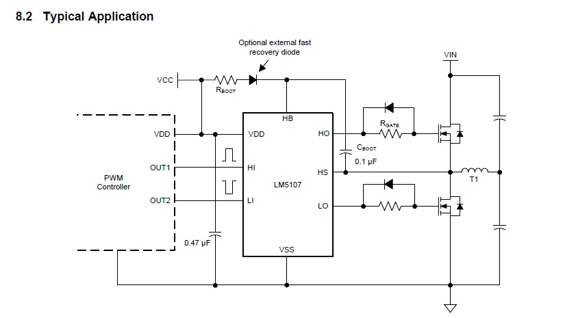
I had to change the mosfet driver in favor of an easier one to solder (LM5107 of Texas), but the working principle is the same. The only difference is that the bootstrap diode D1 is integrated in the driver, so I removed it from my circuit.
Program:
I did the PWM programming on Arduino in advance, for both buck converter und boost converter mode.
I have two PWM output, pin10 and pin9, controlling respectively the high and low input of the mosfet driver. I never need both at the same time, and because of the initialization, the program goes directly in buck mode (PWM output at pin 10). To switch between using one pin or the other, I programmed a switch using interrupt on pins D2 and D3. If pin3 contacts ground, the device should go in boostmode, meaning I get a PWM out of pin 9 in the bottom input of the mosfet driver. If pin2 contacts the ground, then the buckmode is set, and there is a PWM output at pin 10 aand none at pin 9.
Here is the code:
#include <avr/io.h>
#include <util/delay.h>
#include <avr/interrupt.h>

const int ModeSwitchHigh = 2;
const int ModeSwitchLow = 3;
const int LowSideMos = 9;
const int HighSideMos = 10;
volatile boolean IsCharging = true;  //True -> Buck converter mode, using only High-side Mosfet. False -> Boost converter mode, using only Low-Side Mosfet
volatile boolean TimerSet = false;


void setup() {
 pinMode(ModeSwitchHigh,INPUT_PULLUP);
 pinMode(ModeSwitchLow,INPUT_PULLUP);
 pinMode(HighSideMos, OUTPUT);
 pinMode(LowSideMos, OUTPUT);

attachInterrupt(digitalPinToInterrupt(ModeSwitchHigh), Buckmode, FALLING);    //Buckconverter mode, Battery loading, High-Side Mosfet
attachInterrupt(digitalPinToInterrupt(ModeSwitchLow), Boostmode, FALLING);    //Boostconverter mode, Battery unloading, Low-Side Mosfet

//InitTimer1
 TCNT1  = 0;
 TCCR1A = 0;
 TCCR1B = 0;

// set to mode 14 fast pwm.
// TCCR1B
// Bit                 7      6      5       4     3      2      1      0
// Bit Name          COM1A1 COM1A0 COM1B1 COM1B0 -----  ----- WGM11  WGM10
// Initial Value       0      0      0       0     0      0      0      0
// changed to          1      0      1       0     0      0      1      0

 TCCR1A = B10100010;

// TCCR1B
// Bit             7     6      5       4       3      2        1       0
// Bit Name      ICNC1  ICES1 ----   WGM13    WGM12    CS12    CS11     CS10
// Initial Value    0     0     0        0       0      0        0       0
// changed to       0     0     0       1       1      0        0       1

 TCCR1B = B00011001;

ICR1 = 159;   //Set Top Value, -> frequency 100 kHz 16 MHz/100kHz-1, 16 MHz internal clock
OCR1A = 50; // init Wert 5 mikro sek
OCR1B = 50;
 }

void loop() {
//Buckmode
 if ((IsCharging == true)&&(TimerSet==false)) {
 // Here Pin 9 stoppen, Pin 10 enable
 TCCR1A &= ~(1 << COM1A1);
 TCCR1A |= (1 << COM1B1);
 digitalWrite(LowSideMos, LOW);
 OCR1B = 100;
 TimerSet=true;
}
 //Boostmode
 else if ((IsCharging == false)&&(TimerSet==false)){
 TCCR1A &= ~(1 << COM1B1);
 TCCR1A |= (1 << COM1A1);
 digitalWrite(HighSideMos, LOW);
 OCR1A = 70;
 TimerSet = true;
  }
}

void Buckmode(){
 IsCharging = true;
 TimerSet = false;
}

void Boostmode(){
 IsCharging = false;
 TimerSet = false;
}
I tested the program on my Arduino nano as standalone (USB powered), and both the PWm outputs as well as the switching function were working very properly.
Problem:
Now, as already said, I’m currently trying to test solely the buck converter mode. As the program directly begins in buck mode, I do not need the switching function yet, at all. There is still absolutely nothing connected to pin 2 an 3, so they shouldn’t do anything, and I should only have a nice PWM at my pin10 output.
But I don’t.
Each time I tried to make the buck converter functions, the Arduino would directly switch the output PWM to pin9. The compare value is the one I set for this PWM output in the main loop (boost converter mode) of the program, not in the initialization, so it really seems that the Arduino had switched by itself.
Tests:
I tried to swap the connections of pin 9 and pin 10, to try and get some PWM at the high input of my mosfet Driver, even with this bug, but then the error doesn’t appear anymore, my PWM is nicely at pin 10, and I get nothing at pin 9 now connected with the top input of the driver.
If I actively switch between the mode by making a contact between gnd and pin 3 or 2, the PWM at the pin connected to the low input of the driver stops (which it should), but I do not get any PWM from the other pin, and then I cannot get any PWM from either of the pins anymore.
In short:
Essentially, whatever I try, I cannot get a PWM in the high Input of mosfet driver. The PWM mode will be either switched, or I won’t get any PWM at all anymore.
I did not find many helpful ressources in internet to this weird problem. Some people had self-switching arduinos problem because there was no pull up in the switch input, but I think this is solved by the
“pinMode(ModeSwitchHigh,INPUT_PULLUP);
pinMode(ModeSwitchLow,INPUT_PULLUP);" lines.
What’s more, it seems the self-switching is only a consequence of whatever problem there is, that prevents the high input of the mosfet driver to get a PWM.
When working on the code, I got help with a problem here, though I’m not sure whether this topic will be of any help.