-- Part 2 ----
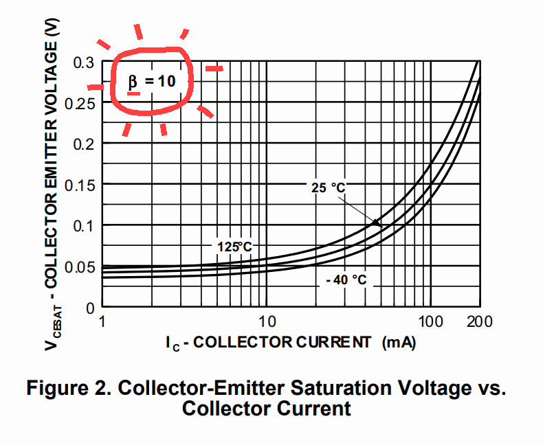
But, what if the motor needs more current to properly function? Well, that's going to be a problem. Unless we bend the "rules" a bit. Does the Beta really need to be 10? With the datasheets that I found for this transistor, it's hard to tell, so some experimentation will be needed [caveat: this is fine for a personal project, but if this is for something that will go into production and be sold -- then you can get yourself into trouble designing something that doesn't adhere to the datasheet]. BUT, if experimentation is acceptable, then, try upping the base resistor. For instance, let's see what value of base resistor would need to be to drive the motor at a 300mW transistor dissipation level. First, let's guess at what the VCE(sat) will be: How about 1V
To figure out the collector current when the Emitter-Collector voltage is at 1V and the power dissipation is at 300mW, use this formula (derived from P=IE):
I = P/E = 300mW/1V = 300mA
Oops, that's not any better. How about if the VCE(sat) is 0.8V:
I = P/E = 300mW/0.8V = 375mA
So, you might be able to squeeze a little more drive out of that transistor, by increasing the Beta, but only if doing so doesn't raise the VCE(sat) much higher than 0.7V -- only experimentation will tell.
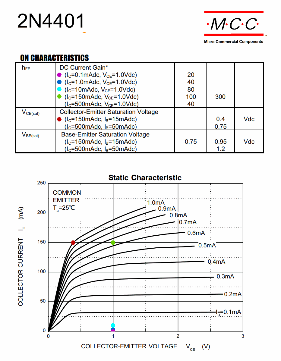
But, the better option is a beefier transistor. How about the 2SC6097 with VCE(sat) more like 150mV at IC=1A and IB of only 50mA [i.e. a **ß** of 1A/50mA = **20**!]
And, with a Collector Dissipation of 800mW, we have some wiggle room! After all, this transistor is rated to 3A!
So, let's see what we can do with a 20mA Arduino output:
20mA*20 = a collector current of 400mA
The 2SC6097 datasheet has an IC - VCE "characteristics curve", so we can do a better job of designing this thing (and be in compliance with the datasheet!). If you look at the 20mA line, you can see what the VCE will be for different Collector Currents! Notice that at an IC of 0.5A, the VCE is less than 0.1V! And, even at 1A it's around 0.13V. So, to get a ballpark, lets see what the IC is when the VCE is 0.13V and the power dissipation in the transistor is 800mW/2 = 400mW:
I = P/E = 400mW/0.13V = 3A
So, we should be able to drive this transistor with a mere 20mA and be OK, even if the current demand is greater than 400ma -- i.e. at Betas greater than 20, because, even if the VCE increases from what it would be at Beta 20, it's already so low that there isn't as much impact on power dissipation as there was with that BC337, with a VCE of 0.7V [which is high, for a switching transistor]. In fact, were good all the way up to 3A. And, even better, such high currents, if ever present, should only be intermittent stall current [we hope], and when the motor is buzzing along in normal use, the current will only be in the 300mA range -- or perhaps something higher, if a load is placed on the motor. At any rate, our little transistor appears capable of handling it all.
BTW: remember all that stuff about Beta in the active region? What that value [300 to 600 for the 2SC6097] means, is, the beta can go that high, but the higher the beta, the further the transistor is from that full turn-on point called saturation. And, in fact, if the Beta reaches the maximum current gain possible for that transistor (with some particular Collector current and Collector to Emitter voltage), then the transistor is no longer saturated, but is, instead, in that region called, "active", that is used more for linear amplification type applications. And, when designing a transistor application, it's all a bunch trade offs. When switching, the beta doesn't, necessarily need to be at 10. That's just the best tradeoff for minimal VCE and the lowest power dissipation. But, if, say you need to drive more current with a limited base current (like in the case of trying to drive things with an Arduino), then you can up the Beta (by increasing the base resistor), as long as you're not going to fry the transistor in the process. And, in those cases, adding a heatsink may help.
This little tutorial is just a 101 -- it's a far bigger subject, but hopefully this will give you a leg up on figuring out how to drive things with a bipolar transistor.
And, I tend to lean more towards a MOSFET when driving anything with even a modest current demand.