I am trying to build a 4 wheel mobile robot. Right now, I am trying to set up the DC Motors with my encoders. Cheap ones but it should produce some metrics white spinning. I am having some issues with the language or the hardware I have placed. I dont know.
My issue is while reading the values from the encoders. Please find attached a youtube video and the code running.
What' s expected
I am expecting to have a LED turn on/off as the Encoder LED turn on/off. It seems that the onboard ARduino LED is not allied with the motor encoder LED. It feels like there is a delay here? Am I missing something? I have also used RISING & CHANGE.
What have I tried
I have tried to Serial print the rotations variable and see what is happening. I was expecting an output like 1, 2, 3, 4, ... just like the LED in the motor encoder turn on. So If I see 4 times turn on I would expect 4. But the code procude a value of like 15. Something is messing things up.
I have also tried to minimize the whole light from the room.
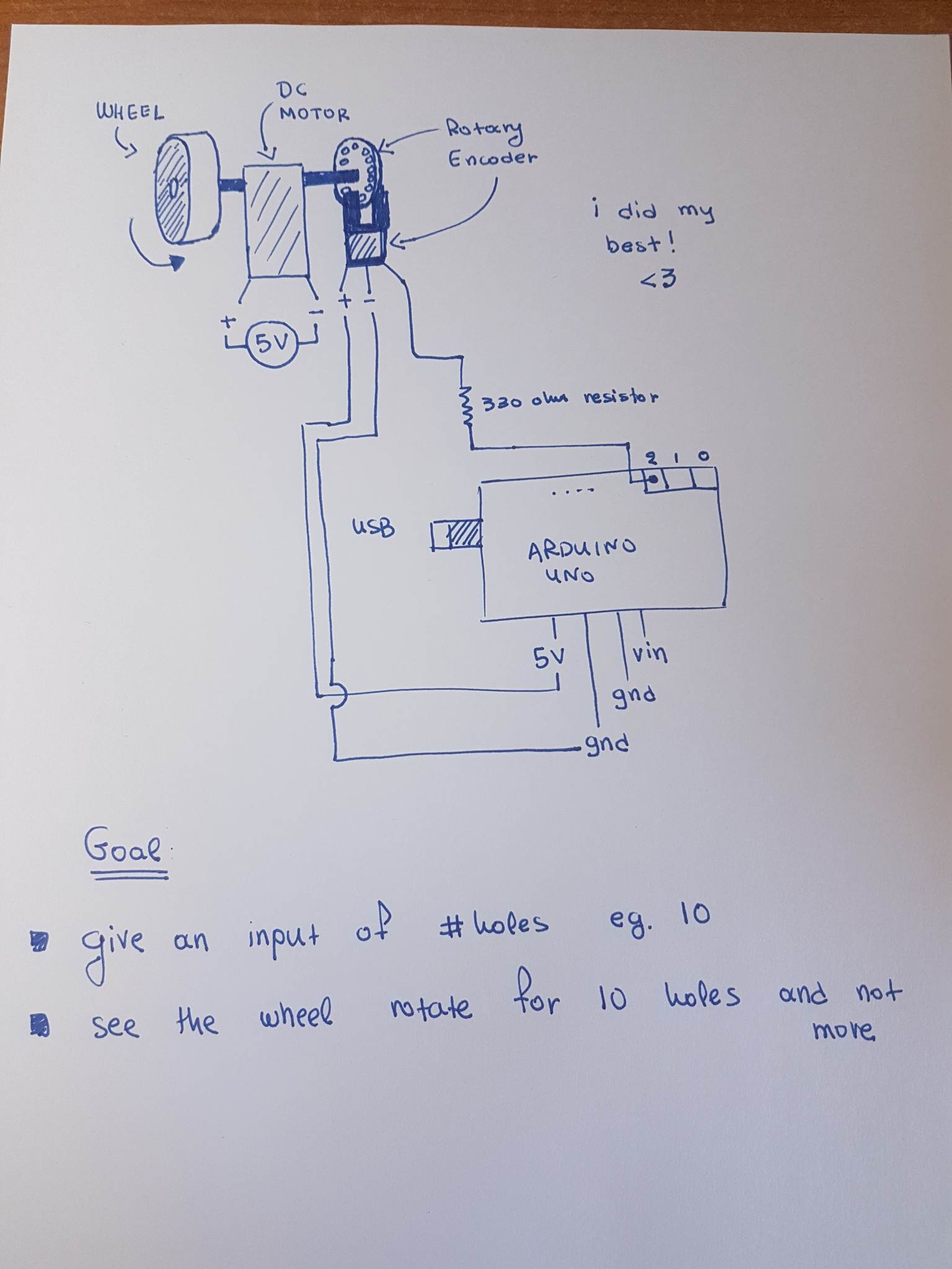
I have also tried (as you can see in the video - my last test) to add a 330Ohm resistor. Nothing changed.
Any variable that is updated in an interrupt routine and read by the main code should be declared volatile. Otherwise, the C++ compiler can make incorrect assumptions about its value when it's attempting to optimise the machine code.
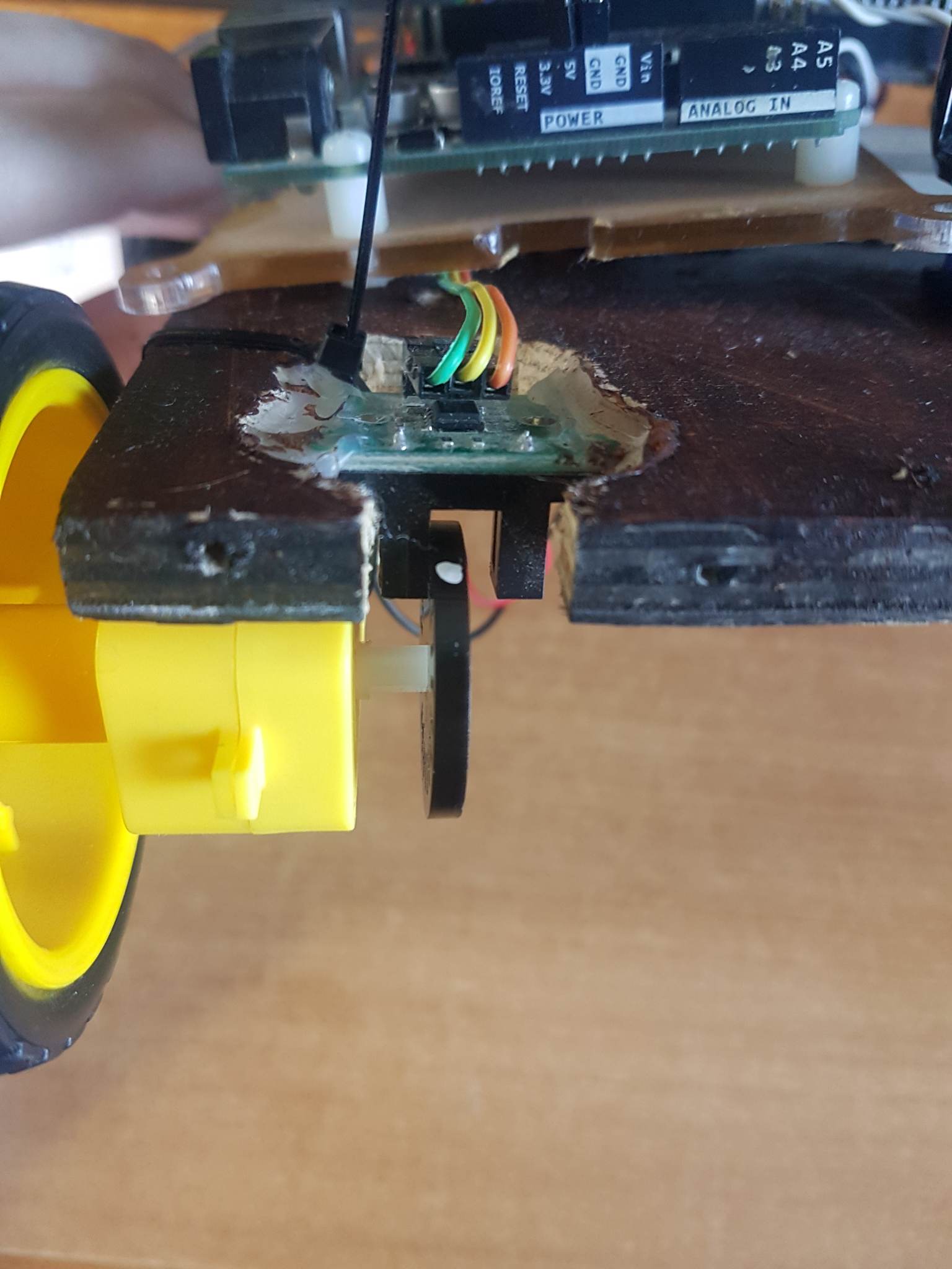
Thanks for the quick response. Actually there is a resistor at the top left corner connected with the green wire. Hard to see, sorry for that.
I tried INPUT_PULLUP and I have the save result.
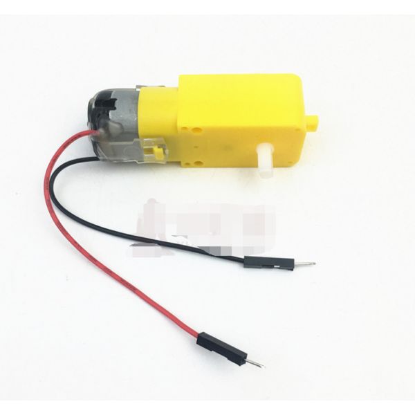
Specifications:
Operating voltage: 3V~12VDC (recommended operating voltage of about 6 to 8V)
Maximum torque: 800gf cm min (3V)
No-load speed: 1:48 (3V time)
The load current: 70mA (250mA MAX) (3V)
This motor with EMC, anti-interference ability. The microcontroller without interference.
Size: 7x2.2x1.8cm(approx)
I see a bare wire stuck in one of the Uno pin sockets. Is that the leg of the resistor? That probably won't make a reliable contact. Also sounds like you are using it as a series resistor, in series with an Arduino input pin? That won't do any good. Arduino input pins have an input impedance (resistance) of many megaOhms. An extra 330 won't make any difference. Why did you add the resistor?
Please post a schematic showing how everything is wired. Use pencil and paper if you are not familiar with any schematic drawing apps.
As I said, I only need a simple "project" that allow me to give as input 21cm and see the wheel spin for a distance of 21cm. Which is actually a full rotation of the wheel encoder since I have 20 holes.
So If I see 4 times turn on I would expect 4. But the code procude a value of like 15.
It may be that the encoder output "bounces", that is goes through several transitions as the opening appears. You have to use a delay or other means to eliminate the problem. Look up "arduino switch bounce" for discussions.
I think it is possible, so I need to add a delay but how much? I dont want to make it loose holes. You know what I mean?
Description: HC-020K speed measuring sensor is a wide voltage, high resolution, short response time, and the switch output speed measurement module. It can test motor's rotational speed with black encoder (measured spec. is related to the encoder, the inner diameter of D type encoder that provided is 4mm, can be used for motor output shaft w/ 4mm diameter, which is TT motor we matched, yellow shell and white axis).
Features:
Module Working Voltage: 4.5-5.5V
Launch Tube Pressure Drop: Vf=1.6V
Launch Tube Current: If<20mA
Signal output: A, B two lines; TT power level;
Resolution: 0.01mm
Measurement frequency: 100KHz
Disc diameter: 24mm
Inner Disc Diameter: 4mm
Encoder resolution: 20 lines
Speed measuring sensor configuration: measure line 1 motor speed
Application: For experiment
I tried use my hand. It seems that it throws many outputs. I mean, I was expecting doing this slowly and I am getting
1
1
1
0
1
0
0
0
1
1
1
0
....
Which means that I have to write some software and clear this out. Which I did. I am throwing away all 1 after the first occurance of 1 until I find a 0. Same story for 0.
I will try now to add a delay with 100ms and see if things do better.
Is there a chance that the speed of the interrupts outpaces the serial output? as they say to avoid using serial print in an interrupt. Which will make your print statements seem incorrect.
Can you add the results to a volatile string or array, then print that on occasion? Just to prove a theory.
It'll be awkward to empty, so you would need to implement some form of "first-in-first-out" management if you wanted to use it in the longer term.
in my routine that is triggered in each interrupt? If you ask me, I believe no. I saw that from someone but this is the job of the interrupt right? Once RISING, I need to increase the counter, nothing more. Need a verification on this.
If you agree, I have the following routine. But delay must not be there right? How can I handle it?
This is not allowed in an interrupt, because delay() depends on interrupts, which are turned off while the interrupt service routine is executing.
In this case, you are lucky that with AVR-based Arduinos, the delay value is simply ignored, so the function call does nothing. Most often when you make this sort of mistake, the processor just hangs.
Another mistake is to access the shared variable "rotations" in the main loop, without protecting it from corruption by the interrupt routine. The way to fix this is as follows:
noInterrupts(); //turn off interrupts
int rotations_copy = rotations; //copy the variable contents
interrupts(); //back on
Serial.println(rotations_copy);  //print or otherwise use the copy.
If your encoder is giving multiple counts for each slot in the encoder wheel, the only easy fix is to buy a better encoder.
I would highly recommend the dronebot workshop episode on this same topic, here is the website with the example Arduino code around using interrupts to measure wheel rotation.
He goes over the reasons to keep interrupts very quick and how/why to disable interrupts as recommended by @jremington
I don't know how the timerone library is written; he's basically using it as a scheduler to trigger a function, and detaching/reattaching the interrupt so as to not derail it. However your suggestion keeps the timer super-light, just like the other two interrupts.
However I'm not going to question most people's favorite uncle of Arduino he's many-shades of excellent.