First, when there is no moisture (DRY) on sensor YL-69, module's YL-38 DC output is ON. And when WET it's OFF. I don"t know why?!
And obliviously, Relay always ON while sensor (YL-69) is totally dry and Vice Versa.
What I did wrong?

First, when there is no moisture (DRY) on sensor YL-69, module's YL-38 DC output is ON. And when WET it's OFF. I don"t know why?!
And obliviously, Relay always ON while sensor (YL-69) is totally dry and Vice Versa.
What I did wrong?
Maybe it is supposed to work that way. Why do you care?
Because in my project most of the time sensor is dry (Project: Detect water and then pump it).
And I care because Relay works on idle (heat himself, electrical consumption?...).
What does one have to do with the other. Who's writing the code ? That's what determines if the relay is on or not.
I don't see the point of your question. Post a schematic and your code and we can talk about it. Otherwise there is nothing to talk about. It's a silly question.
There is no code and no Arduino board.
There is common power supply (5v). It's supply Relay and moisture module YL-38 (which connected to sensor YL-69).
And common wire goes from moisture module YL-38 to relay (Output to Input).
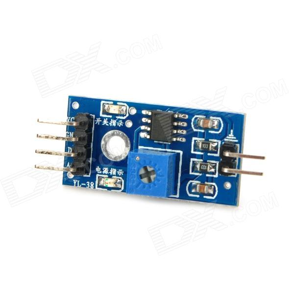
On moisture module YL-38 is potentiometer which determines sensitivity of sensor (when detect water).
Draw a schematic and take a photo of it and post it.
If you use a transistor inverter, when the output of the sensor is OFF, the transistor is OFF, consequently the OUTPUT of the inverter is pulled HIGH and RELAY is ON. When no water is detected, the sensor OUTPUT is ON, transistor is ON, RELAY connected to OUTPUT of inverter is OFF because transistor pulls OUTPUT LOW, thus RELAY is OFF.
Understand ?


There is no use of transistor. I mean transistor is set on board of Relay but I did not set him there. Relay and board are build-in system as you can see on the picture.
May I remove jumper which shortage COM AND GND on Relay and use COM as my Relay input?
yes
Unsuccessful. :~
When I remove jumper which shortage COM AND GND on Relay.
The power of Relays goes down. ![]()
google relay schematic
Go Google yourself! ![]()
You asked for help. I suggested you google it because you obviously don't understand how the relay contacts relate to your pump.
If you are going to respond with that attitude then you're on your own. Everyone else knows why it doesn't work When I said you could remove the jumper I assumed you knew what else you need to do and the schematic would answer that question.
May I remove jumper which shortage COM AND GND on Relay and use COM as my Relay input?
The fact that you would even ask this question indicates you don't have the slightest idea how the relay works, hence my suggestion you look at the schematic . The clue is in one of your posts and since you have refused to post a schematic of your circuit I imagine you will continue to flounder around in the dark.
For the lurkers,
The top IC you are using for on/off and an analog output uses Op Amps. Op Amps are a bunch of transistors, and your using an op amp in a comparator configuration for your digital output. I would have suggested using a simple pull up or pull down resistor on the comparator output before recommending reading on relays.
Also, Its been around 4 years since I've been on this site but the community used to be a lot more helpful than this... I read the above comments as snarky from the helper... and I apologize on behalf of the community.
We should be here to help and help learn. We should give more bread crumbs or just enough info to make them have to go look something up.
We all started somewhere right?