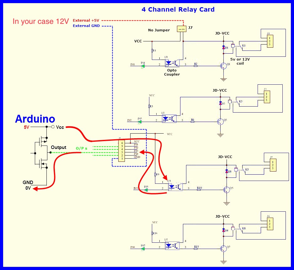
Hello, I am facing a weird problem that when I power off the following device, the relay module is turned ON for a second and turned off. I tried with different module but facing the same issue. Here is the conncetion diagram. BTW the program is working as expected but the only issue while switch off the device.
In the Arduino IDE, use CtrlT or CMDT to format your code then copy the complete sketch.
Use the < CODE / > icon from the ‘posting menu’ to attach the copied sketch.
You can attach a scaled down version that still exhibits the problem.
// Define the relay pin and input pins
const int relayPin = 7;
const int buttonOnPin = 3;
const int buttonOffPin = 4;

void setup() {
  // Set the relay pin as an OUTPUT
  pinMode(relayPin, OUTPUT);
  digitalWrite(relayPin, LOW); // Ensure relay is OFF initially

  // Set the button pins as INPUT with internal pull-up resistors
  pinMode(buttonOnPin, INPUT_PULLUP);
  pinMode(buttonOffPin, INPUT_PULLUP);
}

void loop() {
  // Check if buttonOnPin is connected to GND
  if (digitalRead(buttonOnPin) == LOW) {
    digitalWrite(relayPin, HIGH); // Turn the relay ON
  }

  // Check if buttonOffPin is connected to GND
  if (digitalRead(buttonOffPin) == LOW) {
    digitalWrite(relayPin, LOW); // Turn the relay OFF
  }
}
Yes this is 12v relay module. If I connect both arduino GND and exyernal power supply GND then relay is directly ON though the trigger pin is not activated by the microcontroller.
My primary concern is while power off this entire device the relay is enerzised for a second and then finally switching OFF the entire device as there is no power supply.
Try this change to the sketch below, more than likely won’t make any difference Note you may need to swap the relay N.C. and the N.O. contacts.
#define RELAYon    LOW
#define RELAYoff   HIGH

// Define the relay pin and input pins
const int relayPin = 7;
const int buttonOnPin = 3;
const int buttonOffPin = 4;

void setup() {

  digitalWrite(relayPin, RELAYoff); // Ensure relay is OFF initially

  // Set the relay pin as an OUTPUT
  pinMode(relayPin, OUTPUT);


  // Set the button pins as INPUT with internal pull-up resistors
  pinMode(buttonOnPin, INPUT_PULLUP);
  pinMode(buttonOffPin, INPUT_PULLUP);
}

void loop() {
  // Check if buttonOnPin is connected to GND
  if (digitalRead(buttonOnPin) == LOW) {
    digitalWrite(relayPin, RELAYon); // Turn the relay ON
  }

  // Check if buttonOffPin is connected to GND
  if (digitalRead(buttonOffPin) == LOW) {
    digitalWrite(relayPin, RELAYoff); // Turn the relay OFF
  }
}
You really must only react to the switches when they change state, not to the current switch level.
My requirement is simple. If I connect pin3 to arduino GND pin then need to be enerzised the relay and if I connect pin4 with GND the relay should deenerzised.
But the problem is not with overall functionality but while turning off the device the relay is triggering for a second. I am not sure whether the issue with wiring or sketch.
The sketch below looks at when the switch changes state.
#define RELAYon          LOW
#define RELAYoff         HIGH

#define PRESSED          LOW
#define RELEASED         HIGH

// Define the relay pin and input pins
const int relayPin     = 7;

const int buttonOnPin  = 3;
const int buttonOffPin = 4;

byte lastOnPin         = RELEASED;
byte lastOffPin        = RELEASED;


//================================================^================================================
void setup()
{
  digitalWrite(relayPin, RELAYoff); // Ensure relay is OFF initially

  // Set the relay pin as an OUTPUT
  pinMode(relayPin, OUTPUT);


  // Set the button pins as INPUT with internal pull-up resistors
  pinMode(buttonOnPin, INPUT_PULLUP);
  pinMode(buttonOffPin, INPUT_PULLUP);

} //END of   setup()


//================================================^================================================
void loop()
{
  byte state;

  //=======================================
  state = digitalRead(buttonOnPin);

  if (lastOnPin != state)
  {
    //update to the new state
    lastOnPin = state;

    if (state == PRESSED)
    {
      digitalWrite(relayPin, RELAYon); // Turn the relay ON
    }
  }

  //=======================================
  state = digitalRead(buttonOffPin);

  if (lastOffPin != state)
  {
    //update to the new state
    lastOffPin = state;

    if (state == PRESSED)
    {
      digitalWrite(relayPin, RELAYoff);
    }
  }

  //=======================================
  //poor man's debounce
  delay(50);

} //END of   loop()


//================================================^================================================