I set things up according to this video. Does anyone have experience with this setup and know that it works? The enable pin is not used.
https://m.youtube.com/watch?v=BZH1WkgfOug&pp=ygUVVGI2NjAwIHplbiB0b29sIHRocmVl
I set things up according to this video. Does anyone have experience with this setup and know that it works? The enable pin is not used.
https://m.youtube.com/watch?v=BZH1WkgfOug&pp=ygUVVGI2NjAwIHplbiB0b29sIHRocmVl
I expect it not to work per the video which did not show them working. How do you know it works? Post an annotated schematic showing how you connected everything, include power sources, power, ground, etc.
Then following forum guidelines post your code.
I don't know that it works. That's why I was asking the question. I first wanted to get some experienced knowledge on whether that set up works. After that I would post schematics, etc.
I have experience with a single TB6600 and motor.
The video is correct. You need not connect anything to ENA+ and ENA-.
The rest of the wiring looks correct, assuming the power supply is sufficient to drive all the motors.
That's what I'm worried about, the power supply. Also, trying to test connectivity through the driver. Motor is hard to turn when I put jumper pins into the right wires, but nothing I can test when it's wired to the driver. Open circuit. I think I need to backtrack to one motor and one driver and wait for my adjustable power supply to get in this afternoon. Voltages on the A+/A-, B+/B- poles has me befuddled. My steppers are 1.5a, and 3.3v. Driver wants 9v power. I can't figure out if my 3.3v, 1.5a motors will work. All the research I'm trying to do all step around these issues. I tried looking at a beginners tutorial thread on here on this subject, but still befuddled.
That seems to be absolute minimum voltage of the driver(the edge of a cliff).
Better use a 12- or 24volt supply. Higher voltage = more torque at higher speeds.
A common question/misunderstanding, which has been explained here thousands of times.
If you would have read a few stepper motor posts, you would soon have understood that a stepper driver works like a buck converter. It converts high voltage/low current into low voltage/high current with values that the motor needs at certain speeds.
Leo..
I have read numerous stepper motor posts, and tutorials, etc. Unless it is addressing EXACTLY when I'm doing, sometimes it isn't useful. Didn't know what a buck converter was, and didn't know if it was a typo either at the time you first posted it. I can read stuff before the fact all day long, but until I'm up against it, it's not going to fall together to where I can grok it. I learn by trying to solve problems, not by studying. If I study based on what is confronting me, then it goes in in a more useful manner.
Given all that, I appreciate all the input you folks are giving me. Sorry to be annoying sometimes. I have something sort of like ADHD, and taking in new stuff can be a bit chaotic.
I was using a 12v 1.25a power source, but don't know if it wasn't enough oomph, or something else going on. I think for one thing, I bit off too many things at once to attempt going with a bipolar stepper. Took me a little bit to get the unipolar working when I did it.
I’ve had similar issues with TB6600 drivers. Make sure your wiring and power supply are stable. Also, double-check the pulse and direction signal connections from your Arduino to the driver. Sometimes adjusting the microstep settings on the driver helps with smoother operation. Hope this helps!
I was checking the voltage levels on this trickle charge power supply I was making do with, until I could get a better one, and it was jumping all over the place. My DMM might be crappy though. Got to pull out my other one. I'm definitely getting into the area of debugging hardware here. But, that's how I learn.
An old 19volt laptop supply is easy to get from a thrift store.
Leo..
I have different ones around here. I'm not comfortable enough yet with what things will risk burning things out. I read different warnings about different components not to apply too much voltage.
Max supply voltage for the TB6600 is 42volts (9 to 42volt).
Motor voltage has little to do with driver voltage.
Leo..
That explains a lot. Consider reading a data sheet for a part, it will be difficult at first but it will give you a lot of information you will need such as voltage, current, capacity, etc.
Been reading data sheets. Operating voltage is pretty much not listed for stepper motors. Thus I have to ask to try to clear up my confusion. So little gaps in knowledge are getting filled in, sorta.
Now that I’ve been told about the grey area regarding stepper motor operating voltages, asking the question on Google Ai gave me a lot to go on. Duh. I just had to be informed it was a grey area and not just left out data no matter where I looked. Just found this.
AT LAST, a formula.
Power Calculation:
Calculate the required power using the formula P = n*I*V*1.2, where n is the number of phases, I is the current, and V is the voltage.
SUCCESS. Simplified to one motor, one driver. Looks like I had the dir and step wires reversed. Plus I now have a little power supply that isn't jumping around like a kangaroo on meth.
Not as simple as that.
The driver varies coil current between 0% and set current (dip switches), depending on step position and microstepping. There is usually a table for that in the datasheet.
All you need to worry about is to set the driver to 1.5Amp or less.
Leo..
It is set to 1.5 amp. Your input got me over some worry, and pointed me to some articles that let me know I wasn't going to burn my house down. Plus I got a stable power supply. Motor is working. Now looking into AccelStepper and how to use it.
People here seem to prefer MobaTools.
Ad if you need help, the author is a member here.
Install via LibraryManager of the IDE.
Leo..
Still trying to debug this stepper and TB6600.
Motor specs:
Nema 17 Stepper Motor 40MM Bipolar 1.5 A 42Ncm (59.47oz.in) 42 Motor 1.8 Degree 2 Phase 4-Lead Nema17 Motors Parameters]: Body Length: 40mm/1.58inch; Step Angle: 1.8 degree; Phase: 2; Rated Voltage: 3.3V; Rated Current: 1.5A; Phase Resistance: 2.2Ω; Phase Inductance: 4.5mH; Holding Togque: 42N.cm (59.47oz.in); Detent Togque: 1.8N.cm (2.55oz.in); Weight: 280g.
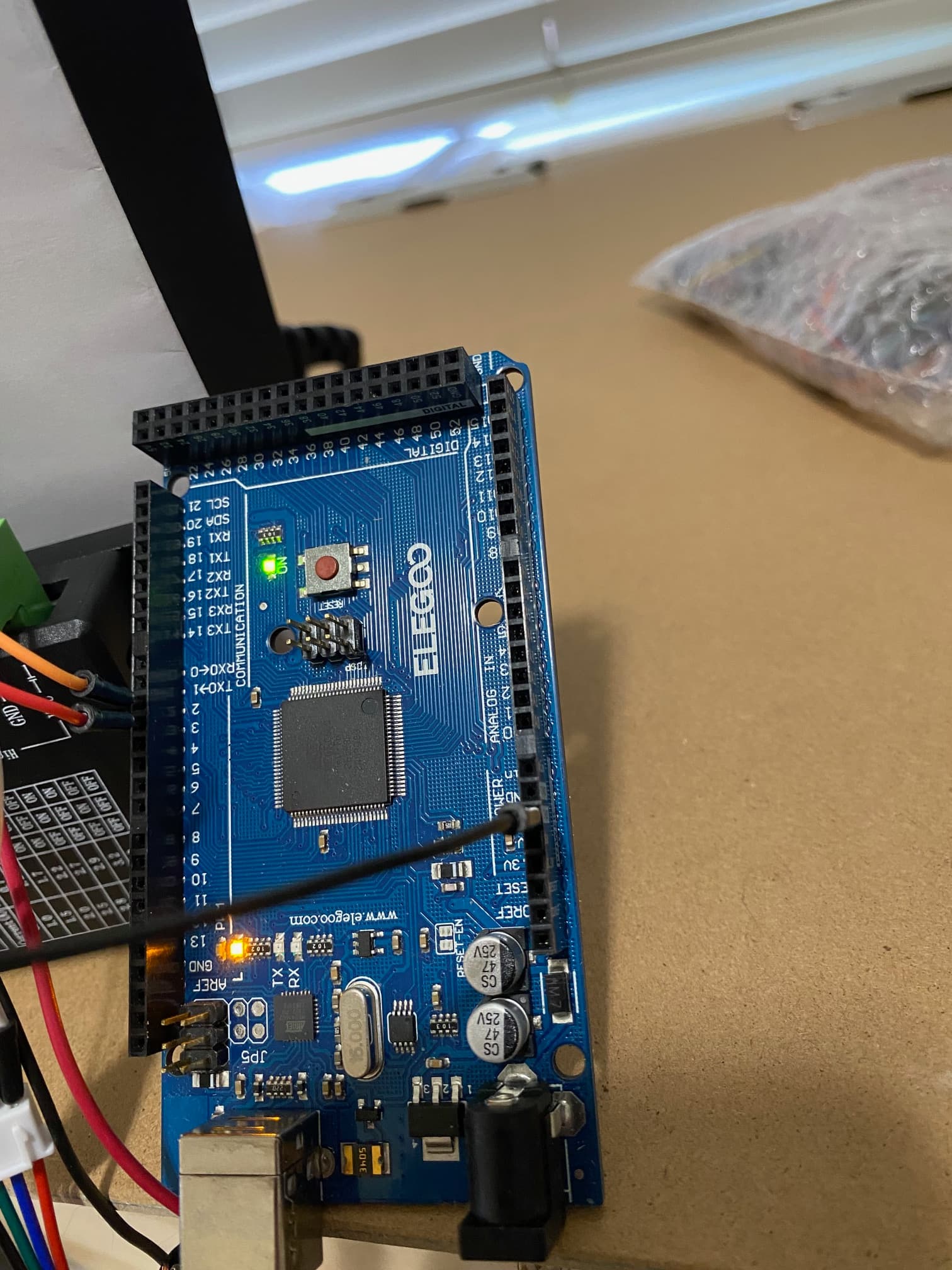
Arduino: Mega board
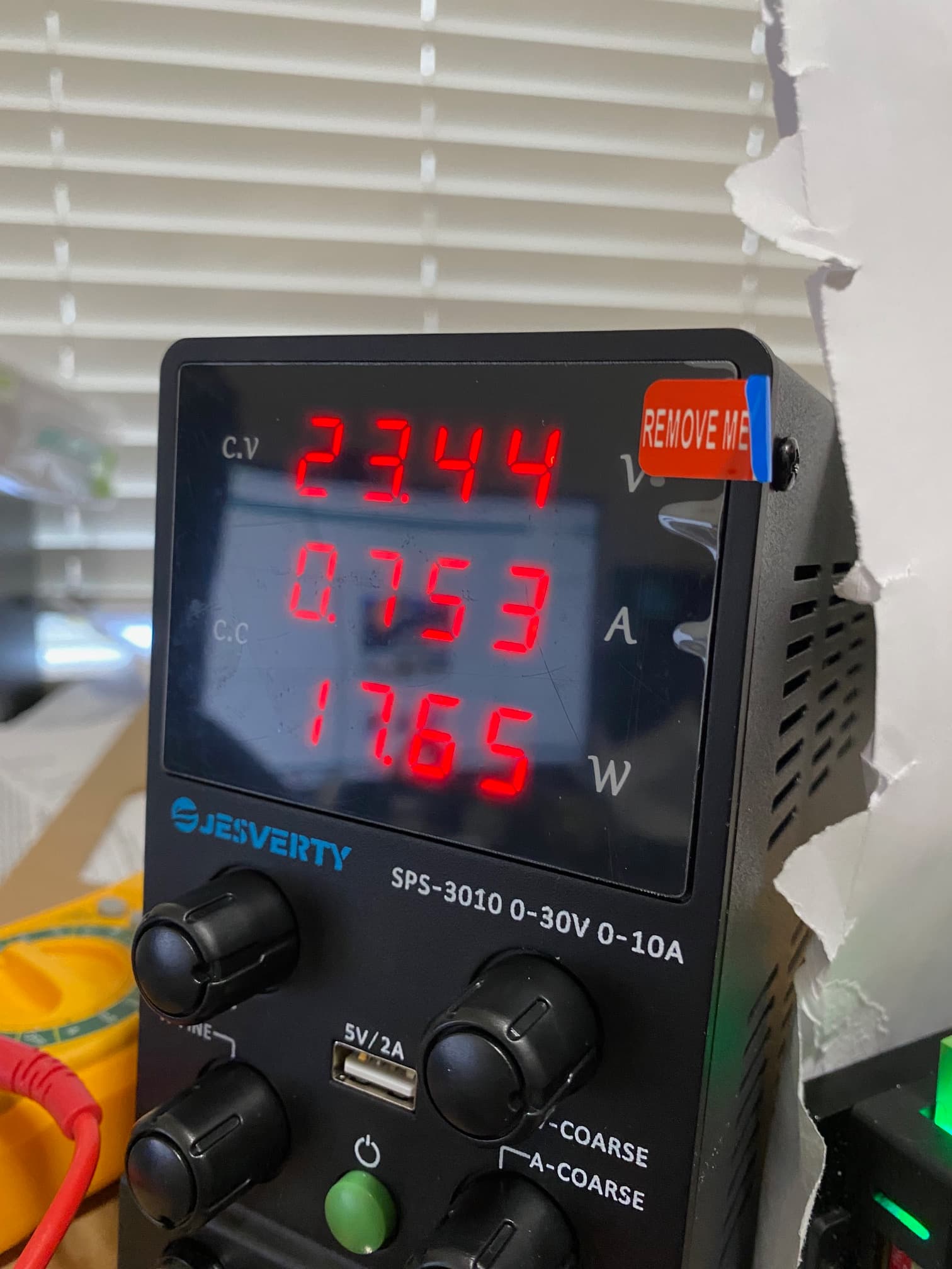
Power Supply settings
Pin Outs on Mega board
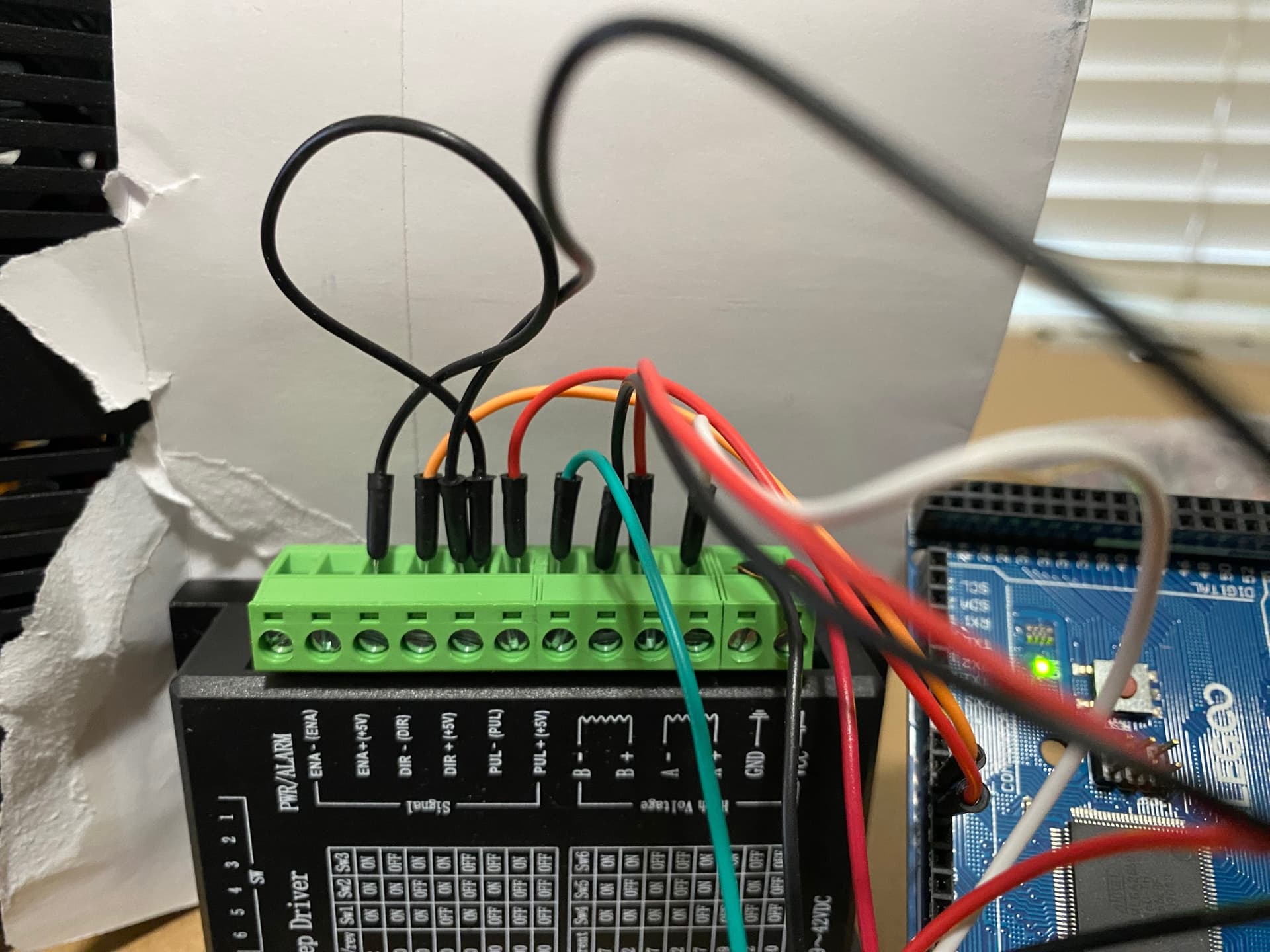
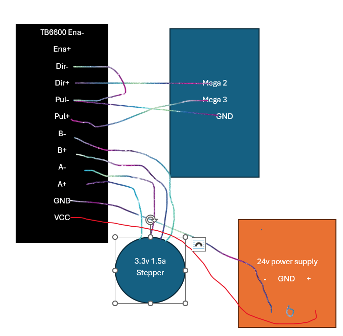
Pin Ins to TB6600
TB6600 Pul-, Dir- joined together with black jumper.
Mega GND -> TB6600 Pul - (black jumper)
Mega Pin2-> TB6600 Dir+ (orange jumper)
Mega Pin3 -> TB6600 Pul+ (red Jumper)
Stepper White wire 1 -> TB6600 A+
Stepper Red Wire 2 -> TB6600 A-
Stepper Black Wire 3 -> TB6600 B+
Stepper Green Wire 4 -> TB6600 B-
The actual wire colors got remapped to the above colors when I plugged external jumpers into them.
Here's the code:
#include "AccelStepper.h"
#define dirPinX 2
#define stepPinX 3

long StepsPerRevolution = 200;

long Revolutions = 6000;
long TotalSteps = StepsPerRevolution * Revolutions;

#define motorInterfaceType 4

AccelStepper stepperX = AccelStepper(motorInterfaceType,stepPinX, dirPinX);

void setup() {
Serial.begin(9600);
Serial.println(TotalSteps);

stepperX.setMaxSpeed(300);
stepperX.setAcceleration(80);

}

void loop() {

  stepperX.moveTo(TotalSteps);

  stepperX.runToPosition();

  Serial.println(stepperX.currentPosition());
}
I tried this with 12v, 1.25a, and I was getting slow and ragged results, turned it up to 24v, and am getting slow and ragged results. No appreciable speed increase over 100 maxSpeed.
Is my motorinterfaceType wrong? I tried DRIVER, but same problem. Only smooths out when I set maxSpeed to 100. There MIGHT be something misconstrued with the motorinterfaceType and the mapping of pins 2 and 3, but the documentation is not clear yet.