Decoding camshaft sensor

Hello,

I have just picked up an Arduino nano for a project. So i am a complete newbie to arduino, and even programming.

I want to interpret the signal pattern attached in this image.
As you can see the sensor has two signals, the "ident" signal is occuring once in a revolution and the "cyl" signal occurs 6 times in a revolution.

"ident" is the TDC of #1 cylinder.
"cyl" is the TDC of all 6 cylinders.

camshaft signals

The goal of the project would be to use the arduino to drive a wasted spark coil pack instead of the distributor. (which is generating theese signals via hall sensors and vanes)
The distributor would remain connected to the ECU as is, thus the ECU can function as usual, and output an ignition trigger signal. ( timing the spark event and coil dwell)
The engine needs 3 wasted spark coil packs, each firing two cylinders. (1-4, 5-2,, 3-6)
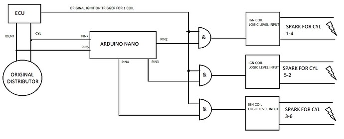
I could drive the coil packs with the original trigger signal from the ECU and a cylinder pairs signal from the arduino.
For example:
each coil pack has a CMOS AND gate driving it. A input of all the gates is the ECU trigger signal.
B input is an output from arduino.
The ECU knows which cylinder needs to be ignited, outputs the ignition trigger signal.
The arduino knows also which cylinder is at TDC, for example its cylinder 5 at the moment. Arduino outputs a digital signal drivng the AND gate for 5-2 cylinders coil.

I have written this code and tested it. It works, sort of.
It needs a synchnorization bit to avoid sending the wrong output if its not certain which cylinder is next. I have tried several ideas that didnt work(commented in the program) , then came up with the last one which did seem to work.
Then i have modified something in the program, now the sync variable never goes to 1, only if i reset the board, then it goes to 1 for 3 pulses.

I hve tried debugging this for hours with no avail.

Please advise. If you have another ideas for implementing this "camshaft decoder", i am open for it.

code:


const int ident = 6;    //pin 6 = cylinder identification input
const int cyl= 7;       //pin 7 = cylinder strobe input
const int cyl14 = 2;     //pin 2 = 1-4 cylinder output
const int cyl52 = 3;    //pin 3 = 5-2 cylinder output
const int cyl36= 4;       //pin 4 = 6-3 cylinder output


int identState = 0;   
int cylState = 0;       
int LastIdentState =0; 
int LastCylState = 0; 
int sync = 0;
int count = 0;
bool identhigh;
bool cylhigh;
int counterCyl = 0;
int counterIdent = 0;
int counterIdentHigh = 0;
int counterIdentLow = 0;


void setup() {
  //define IO pins
 pinMode(cyl14, OUTPUT);
 pinMode(cyl52, OUTPUT); 
 pinMode(cyl36, OUTPUT);
 pinMode(ident, INPUT_PULLUP);
 pinMode(cyl, INPUT_PULLUP); 
Serial.begin(2000000);   //9600 baud made the program run slow, lost sync at about 1500rpm
}


void loop() {
  
//read inputs
identState = digitalRead(ident);
cylState = digitalRead(cyl);

//detect falling and raising edges
  
  if (identState != LastIdentState) {
    // if the state has changed, increment the counter
    if (identState == HIGH) {
      // if the current state is HIGH then the vane is in front of the hall sensor
      counterIdent++;
      identhigh=1;
      counterCyl=0;
      /*Serial.print("number of revolutions: ");  //the ident input generates 1 pulse/rpm
      Serial.println(counterIdent);
      */
    } else {
      // if the current state is LOW then the vane is NOT in front of the hall sensor
      identhigh=0;
      counterCyl=3;
    }
    
    
  }
  
LastIdentState = identState;   //save last known state


  if (cylState != LastCylState) {
    // if the state has changed, increment the counter
    if (cylState == HIGH) {
      // if the current state is HIGH then the vane is in front of the hall sensor
      counterCyl++;
      cylhigh = 1;
      Serial.print("no of current cylinder: ");  ///serial printing is only used for debugging prposes
      Serial.println(counterCyl);
      Serial.print("sync: ");
      Serial.println(sync);
      Serial.print("identhighcount: ");
      Serial.println(counterIdentHigh);
           Serial.print("identlowcount: ");
      Serial.println(counterIdentLow);
      Serial.println(counterCyl - counterIdentHigh);
      Serial.println(counterCyl - counterIdentLow);

  if (LastIdentState == HIGH) {
    counterIdentHigh++;
  }else {
    counterIdentHigh = 1;
  }
    
    if (LastIdentState == LOW) {
    counterIdentLow++;
  }else {
    counterIdentLow = 4;
    } 

    }
    else {
       // if the current state is LOW then the vane is NOT in front of the hall sensor
      cylhigh = 0;
    }
     
    
  }
  

  LastCylState = cylState;  //save last known state


//sync
if ((counterCyl - counterIdentHigh == 0) || (counterCyl - counterIdentLow == 0)){

  sync = 1;
}
else {
  sync = 0;
}

/*if ((counterCyl >= 1 && counterCyl <= 3 && identhigh == 1) | (counterCyl <= 6 && counterCyl >= 3 && identhigh == 0 ) ){
  
  sync = 1;
} else {
  sync = 0;
}
*/
/*if (counterCyl >6){
  counterCyl = 0;
}*/
/*if (counterCyl <= 6 && counterCyl >= 4 && identhigh == 0 ){
  sync = 1;
} else{
  sync = 0;
} */


/*if (counterCyl > 5 &&  identhigh == 1 && cylhigh == 0){
  counterCyl = 0;
}
*/


//writing outputs depending on where the counter sits and sync is ok

if ((counterCyl == 1 || counterCyl == 4) && sync == 1  ){
  
    digitalWrite(cyl14, HIGH); 
    

}
else {
  digitalWrite(cyl14, LOW);
}
if ((counterCyl == 5 || counterCyl == 2) && sync == 1 ){
  
     digitalWrite(cyl52, HIGH);
  }

else {
  digitalWrite(cyl52, LOW);
}

if ((counterCyl == 3 || counterCyl == 6) && sync == 1 ){
   
     digitalWrite(cyl36, HIGH);
}

else {
  digitalWrite(cyl36, LOW);
}

//end of loop
}


1 Like

I am not sure why, but my sync string doesnt perform the OR command.

if ((counterCyl - counterIdentHigh == 0) || (counterCyl - counterIdentLow == 0)){

  sync = 1;
}
else {
  sync = 0;
}

I have been watching via serial printing the "counterIdentHigh" and "counterIdentLow" values, one of them are always the same value as "counterCyl ", so the IF line should result in writing sync=1 not the else condition, but it doesnt.

If your car has variable valve timing it won’t work ( cam sensors often associated with vtec motors )
All the electronic systems I’ve seen use a crank position sensor , usually a toothed wheel with a missing tooth ( which gives the absolute crank position ) - you get better resolution as a the crank is moving twice as fast and more pulses , and it’s crank position that you are really interested in .
Have a google of Megajolt.

Don’t forget you will need load and rpm advance . The existing distributer will be looking after advance so your cam and distributer signals will move relative to each other .Distributers create a lot of timing scatter due to wear , so better not to use it .

Megajolt

The car has fixed timing, ie no VVT or anything. Its a Mazda KL V6 engine.
The ignition timing and such is done by the ECU entirely, the stock distributor just allows a "window" of possible spark advance and retard by sweeping the ignition lead post with the rotor for X amount of degrees of rotation, which is the same for the 6 TDC vanes in the sensor.
So this project would be working like a "digital" distributor for wasted spark, the ecu controlling advance and retard, dwell, and timing of the spark event, the arduino output just enabling the original ECU signal to reach the desired coil based on where the cam signals are.

Ok that’s a bit more detail , so presently the distributer is just directing the signal to give the spark and the HT .

So you need something to get the ignition pulse and feed it to a coil pack , replacing the distributer .
You really need to know the system
You have in great detail ( for example Ford Edis based systems can detect faults in the coil pack, if you remove your coil system then you might get issues ?).

Bit advanced this ! It might be worth looking around internet - eg this engine swaps into max-5 , what have they used ?

Personally - why do you want to do this ?

Fortunately i have been working on this engine platform for about 5 years now, doing engine swaps, ECU replacemenets (for OEM units but from another platform) and engine harness rewirings.

I am pretty sure know the ins and outs of this control system. The ECU has no information from the distributor except for the two hall signals.

The distributor has an inbuilt igniter and ignition coil, which are powered directly by the main relay, the ECU just simply drives the igniter with a TTL pulsed signal, giving the spark timing, and the distributor is simply directing the spark to the desired HT lead in the time window, which is given by the width of the rotor face area.

All mx5 and other platforms that never had this engine option are using custom harnesses with standalone EMS. They usually run 36-1 crank wheels, and COPs.
I could go to standalone and be done with this problem, that would enable me to run wasted spark or COP ignition, but i dont want to ditch the factory ECU.

I've been playing around with the code, writing the sync section differently, and printing the variables.

if (counterCyl-counterIdentHigh==0){
  synchigh=1;
  }else {
    synchigh=0;
  }


if (counterCyl-counterIdentLow==0){
  synclow=1;
  }else {
    synclow=0;
  }


if (synclow==1||synchigh==1) {

  sync = 1;
}
else {
  sync = 0;
}

the serial print goes like this:

      Serial.print("no of current cylinder: ");  
      Serial.println(counterCyl);
      Serial.print("identhighcount: ");
      Serial.println(counterIdentHigh);
      Serial.print("identlowcount: ");
      Serial.println(counterIdentLow);
      Serial.print("sync: ");
      Serial.println(sync);
      Serial.print("synchigh: ");
      Serial.println(synchigh);
      Serial.print("synclow: ");
      Serial.println(synclow);

an example of the serial monitor output:

no of current cylinder: 2
identhighcount: 2
identlowcount: 4
sync: 0
synchigh: 0
synclow: 0

as per this,

if (counterCyl-counterIdentHigh==0){
  synchigh=1;
  }else {
    synchigh=0;
  }

should be TRUE, as CounterCyl value is 2, counterIdentHigh value is also 2, and 2-2=0, the if statement should be true, and write synchigh to 1, but in the serial monitor it shows synchigh = 0.

What am i missing??

Finally got the problem.

  if (LastIdentState == HIGH ) {
      counterIdentHigh++;
   }else  {
      counterIdentHigh = 0;
   }

in the else, counterIdentHigh needed to be set to 1, not 0.
I have been tricked by the placement of the serial printing in the program. It was before the counter incrementing part, so it did not print the newest values.

this is the current code:


const int ident = 6;    //pin 6 = cylinder identification input
const int cyl= 7;       //pin 7 = cylinder strobe input
const int cyl14 = 2;     //pin 2 = 1-4 cylinder output
const int cyl52 = 3;    //pin 3 = 5-2 cylinder output
const int cyl36= 4;       //pin 4 = 6-3 cylinder output


int identState = 0;   
int cylState = 0;       
int LastIdentState =0; 
int LastCylState = 0; 
int sync = 0;
int count = 0;
int identhigh = 0;
int cylhigh = 0;
int counterCyl = 0;
int counterIdent = 0;
int counterIdentHigh = 0;
int counterIdentLow = 0;
int synchigh = 0;
int synclow = 0; 


void setup() {
  //define IO pins
 pinMode(cyl14, OUTPUT);
 pinMode(cyl52, OUTPUT); 
 pinMode(cyl36, OUTPUT);
 pinMode(ident, INPUT_PULLUP);
 pinMode(cyl, INPUT_PULLUP); 
Serial.begin(2000000);   //9600 baud made the program run slow, lost sync at about 1500rpm
}


void loop() {
  
//read inputs
identState = digitalRead(ident);
cylState = digitalRead(cyl);

//detect falling and raising edges
  
  if (identState != LastIdentState) {
    // if the state has changed, increment the counter

    if (identState == HIGH) {

      // if the current state is HIGH then the vane is in front of the hall sensor
      counterIdent++;
      identhigh=1;
      counterCyl=0;
     
    } else {
      // if the current state is LOW then the vane is NOT in front of the hall sensor
      identhigh=0;
      counterCyl=3;
    }
    
    
  }
  
LastIdentState = identState;   //save last known state


  if (cylState != LastCylState) {
    // if the state has changed, increment the counter
    if (cylState == HIGH) {
      // if the current state is HIGH then the vane is in front of the hall sensor

      counterCyl++;
      cylhigh = 1;
    

   if (LastIdentState == HIGH ) {
      counterIdentHigh++;
   }else  {
      counterIdentHigh = 0;
   }
    
  if (LastIdentState == LOW ) {
      counterIdentLow++;
   }else {
      counterIdentLow = 3;
   } 
if (counterIdentHigh > 3){
  counterIdentHigh = 0;
}
if (counterIdentLow >6 ){
  counterIdentLow = 3;
}

  Serial.print("no of current cylinder: ");  ///serial printing is only used for debugging prposes
      Serial.println(counterCyl);
     /*Serial.print("no of revolutions: ");
      Serial.println(counterIdent);
      Serial.print("identhighcount: ");
      Serial.println(counterIdentHigh);
           Serial.print("identlowcount: ");
      Serial.println(counterIdentLow);
        Serial.print("sync: ");
      Serial.println(sync);
      Serial.print("synchigh: ");
      Serial.println(synchigh);
      Serial.print("synclow: ");
      Serial.println(synclow); */
                                                                    

    }
    else {
       // if the current state is LOW then the vane is NOT in front of the hall sensor

      cylhigh = 0;
    }
     
    
  }
  

  LastCylState = cylState;                          //save last known state


if (0==(counterCyl-counterIdentHigh)){
  synchigh=1;
  }else {
    synchigh=0;
  }


if (0==(counterCyl-counterIdentLow)){
  synclow=1;
  }else {
    synclow=0;
  }


if ((synclow==1|synchigh==1) && counterIdent>1) {

  sync = 1;
}
else {
  sync = 0;
}

if (counterIdent>5){
  counterIdent=2;
}

//writing outputs depending on where the counter sits and sync is ok

if ((counterCyl == 1 || counterCyl == 4) && sync == 1  ){
  
    digitalWrite(cyl14, HIGH); 
    

}
else {
  digitalWrite(cyl14, LOW);
}
if ((counterCyl == 5 || counterCyl == 2) && sync == 1 ){
  
     digitalWrite(cyl52, HIGH);
  }

else {
  digitalWrite(cyl52, LOW);
}

if ((counterCyl == 3 || counterCyl == 6) && sync == 1 ){
   
     digitalWrite(cyl36, HIGH);
}

else {
  digitalWrite(cyl36, LOW);
}

//end of loop
}

Added protection in the sync line.

if ((synclow==1|synchigh==1) && counterIdent>1) {

  sync = 1;
}
else {
  sync = 0;
}

This ensures that the sensor had at least one full revolution (counterIdent>1) before giving any output. This had to be done because when resetting the board, no matter where the sensor was, it always gave cylinder no 1 as a result.

I still need to come up with something to detect if the engine rotates briefly to the wrong direction (ie stalling), as it messes up the counting. If the counting is messed up, it gets reset when approaching cyl #4 or cyl #6 via the "ident" signal, but it can output cyl #2-3 and #5-6 falsely.

"I still need to come up with something to detect if the engine rotates briefly to the wrong direction (ie stalling), as it messes up the counting. If the counting is messed up, it gets reset when approaching cyl #4 or cyl #6 via the "ident" signal, but it can output cyl #2-3 and #5-6 falsely. "

Perhaps this is the reason when cranking the engine with the original ECU, no matter what it needs at least one full rotation to sync cam and crank signals before firing the injectors or the ignition.

So my idea is to detect if there were no state change in a given amount of time, and then reset the "CounterIdent" to zero, thus the sensor had to be rotated again a full revolution before giving any output.

The stall detection time could be lets say:
min crank RPM: 50 -> cam RPM:25
25 RPM is 0,41 revolution/sec (25/60)
in 1 revolution there is 6 cylinder signals, giving 2,46 state changes in a sec (0,41x6)
1 sec/2,46 is 0,406
thus the maximum time between state changes is 40,6ms
if the state change exceeds 40,6ms, then the engine is considered stalled, and "CounterIdent" needs to be set to zero.

Correct me if im wrong, math is not my strong side. :smiley:

The elapsed time counting using millis, and substraction maths needed to detect stalling really slowed down the execution of the program, and the outputs had some dropping out and artifacts over 1500rpm, so i have ditched the stall detection for now.

I have drawn a block diagram for what am i trying to accomplish.

This topic was automatically closed 180 days after the last reply. New replies are no longer allowed.