The project: Two motors controlled by H-Bridge and Pro Micro, using HC12 communication.
The hardware: Receiver: Two motors controlled by H-Bridge and Pro Micro, using HC12 communication. Transmitter: Nano, joystick, and HC12
Expected results: Moving the joystick to any of the 4 quadrants, on X and Y axes should more the motors (for a robot) in particular way.
What happens: Motors react as they should- for the most part - but I cannot get them to stop when the joystick is a idle (center).
Software: For this version, I'm trying create a state machine, using Switch-case statements. Each of the 4 conditions, Forward, Reverse, Left and Right is a case. At the end is a default case if none of the 4 conditions are valid. I'm expecting the motors to stop when none of the cases are valid, ie at idle position, but they continue to run and will change direction at my command.
What I've tried: I tried putting some While and Do-While commands and also the motor stop commands inside the cases but this did not work. In another version I use IF conditionals also with limited success.
// ****Good speed and control but cannot make motors stop
#define Left_PWM 5 // pin 5 Left Motor A1A //recommended is 1A=speed (PWM)
#define LeftDir 3 // pin 3 A1B // 1B=direction
#define Right_PWM 9 // pin 9 Right motor B1A //recommended is 1A=speed (PWM)
#define RightDir 6 // pin 6 B1B // 1B=direction
#define DIR_DELAY 250 // brief delay for abrupt motor changes
//#define SetHC12 8 // HC12 configuration pin low to activate
#include "SerialTransfer.h"
SerialTransfer myTransfer;
struct STRUCT {
int x;
int y;
} testStruct;
int xAxis = 0;
int yAxis = 0;
int c = 0; //case number
int PWM_Slow = 50; //min PWM value that moves motors
int PWM_Fast = 200; //max PWM value max is 255
int deadband = 20; //deadband for around center stick
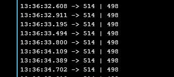
int XCenter = 514; //these are idle values 514 for Joy on Nano
int YCenter = 499; // 499 for joy on Nano
int Xlo = XCenter - deadband; //20 is deadband, amount off center
int Xhi = XCenter + deadband;
int Ylo = YCenter - deadband; //i.e. 498-30=468
int Yhi = YCenter + deadband;
//************************** Setup ********************************************
void setup() {
pinMode(Left_PWM, OUTPUT);
pinMode(LeftDir, OUTPUT);
pinMode(Right_PWM, OUTPUT);
pinMode(RightDir, OUTPUT);
Serial1.begin(19200);
Serial.begin(19200);
myTransfer.begin(Serial1);
}
//*************************** Loop ********************************************
void loop() {
if (myTransfer.available()) {
// keeps track of how many bytes processed from the receive buffer
uint16_t recSize = 0;
recSize = myTransfer.rxObj(testStruct, recSize);
Serial.print(testStruct.x);
Serial.print(" | ");
Serial.println(testStruct.y);
xAxis = testStruct.x;
yAxis = testStruct.y;
}
if(yAxis >= Yhi) { // Stick down= 1022
c = 1;
}
if (yAxis <= Ylo) { // Stick up= 0
c = 2;
}
if (xAxis <= Xlo) { // X Left= 0
c = 3;
}
if (xAxis >= Xhi) { //X Right=1022
c = 4;
}
switch (c) {
case 1: //Motors Reverse Stick down=1022
digitalWrite(LeftDir, LOW);
digitalWrite(RightDir, LOW);
analogWrite(Left_PWM, PWM_Fast);
analogWrite(Right_PWM, PWM_Fast);
break;
//******************Forward********************* Stick up Y=0
case 2: // Motors Forward
digitalWrite(LeftDir, HIGH);
digitalWrite(RightDir, HIGH);
analogWrite(Left_PWM, PWM_Fast); //
analogWrite(Right_PWM, PWM_Fast); //
break;
// X-axis used for left and right control
//*******************turn LEFT******************* X left=0
case 3:
digitalWrite(LeftDir, HIGH);
digitalWrite(RightDir, HIGH);
analogWrite(Left_PWM, PWM_Slow);
analogWrite(Right_PWM, PWM_Fast);
break;
//*******************turn Right******************** x right=1022
case 4:
digitalWrite(LeftDir, HIGH);
digitalWrite(RightDir, HIGH);
analogWrite(Left_PWM, PWM_Fast);
analogWrite(Right_PWM, PWM_Slow);
break;
default:
digitalWrite(LeftDir, LOW);
digitalWrite(Left_PWM, LOW);
digitalWrite(RightDir, LOW);
digitalWrite(Right_PWM, LOW);
break;
} //end switch
} //end loop