Hi All!
I know this might seem trivial but I am a beginner and this forum has been really helpful. I am designing a PCB for a project. It will contain an ATMega328 (with all the relevant oscillators and capacitors), an MPU6050 (accelerometer/gyroscope) and a HC-05 module.
The idea is the values that will be read from the MPU6050 will be processed by the MCU then sent via the bluetooth module to a computer. I was hoping that I could use a detachable/SMT ATMega, upload the program on the arduino board, then place it on the new PCB. Does anyone think this will work? Will the program uploaded, specifically for the MPU6050 on the arduino board still work on the PCB with the new MPU6050 setup?
The aim was to design a minimlist PCB that did not need the bulk of much of the modules and arduino AND I could not program the ATMega chip on the PCB as the TX/RX lines would be connected. If this is overkill, would anyone know any better solutions, or see how I could get around the TX/RX problem?
Any help would be appreciated
Thanks!
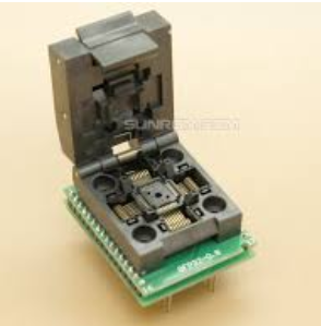
You just need one of the very large ZIF sockets for the SMT ATmega328.
It would make a lot more sense to program the SMT ATmega328P and then solder it to the board rather than just wanting to place it in position. But then it would not really be 'detachable'.
If I understand correctly, you are designing a PCB yourself and that PCB will have the TX/RX pins of the ATMega328 used for other things so you think you need to program the chip and then move it onto your PCB.
I had a similar project. I placed a DPDT switch on the ATMega RX/TX pins so that I could put the switch in a program position, load the program, and then switch to the run position. I used a FTDI module between my laptop USB and the PCB I made and had a 6 pin female header to plug the FTDI into. That would work and has the advantage that ou can debug your program right on the your PCB board. You could also use jumpers instead of the DPDT switch.
Another possibility would be to program the chip using the SPI pins. That should work unless you are pulling MOSI/MISO or SS high/low on your PCB as well.
It sounds like your goal is to keep the board size to a minimum. And you want to program the MCU but think you are limited to removing the MCU because you are using the Tx and Rx pins.
I'm sure there are even simpler ways but, I would simply put two jumpers on your board. These would disconnect Tx & Rx from the other circuits and allow in circuit programming. You may only need a jumper for the Rx, and perhaps with a resistor or two you may not any jumpers at all.
I think you would be dead right about that. You will surely find life easier if you used a Uno with a spare 328P, which is made for just what you seem to have in mind. You could do all your programming in the Uno and probably need not bother with a ZIF socket. Alternatively, I guess you could programme it in situ via jumper pins as suggested, using a USB/TTL adapter.
Use a programmer like ATmel ICE or USBASP. I use most time the Tag Connect cable to program. Also available for ATmel ICE. They use a very small footprint.
This is really ingenious I didn't think of that!
So to understand? I would not need to to have a detachable ATMega chip. I could just design a minamilist PCB around the ATMega, which connects to the bluetooth module and the accelerometer/gyroscope. I would include in the schematic a DPDT switch connected to the ATMega TX/RX pins, and just flick the switch to disconnect the bluetooth module when uploading a program, and connect it when I'm ready to use it?
I copied a picture from an old post and just adapted it - (The TX of arduino connects to RX of bluetooth not TX of bluetooth).
If you have the time could you just briefly confirm this is the right set up?
This is effective, but wouldn't jumpers only work on pins that are sticking out of the board? My PCB wouldn't include any of these as the bluetooth and accelerometer/gyroscope are integrated into one board so they would be directly connected to the ATMega chip.
Without seeing your proposed circuit, it might be possible to add resistors in series with the Tx/Rx/reset that would allow the programmer to overpower these lines yet still allow them to talk to other devices when not being programmed.
For instance, if you added a 5k in series with the Rx and your bluetooth (or something). The programmer would be connected directly to the Rx and be able to drive the Rx pin while not doing any damage to the bluetooth.
Yes, that is the general idea. Your PCB wouldn't have a "USB" connector on it though. It would simply have a six pin female connector where an FTDI Adapter plugs into. (You can find one, for example, at Amazon.) On the project I previously mentioned, I actually had the FTDI Connector in the back panel of the project box. While programming or debugging, the FTDI is plugged into the host USB port and its pins into the female FTDI adapter on your board and the switch is in "Program" mode. To run the project, flip the switch into the "Bluetooth" position. And, the FTDI is connected just like your Bluetooth module: ATMega TX to FTDI RX and ATMega RX to FTDI TX.
Glad you liked the idea!
As I also mentioned, you could do the same thing with jumpers, assuming that you have access to the PCB while programming and debugging and then just leave the jumpers in "Bluetooth" position when the project is finished.
The easiest solution is to use a 28pin dip
328.
Or.. if you don’t need a bootloader why not program your smt version via the icsp lines on the processor?
Someone earlier mentioned using dip switches - if these are too big why not have solder pads so you can first program it , then connect to the other rx/Tx device by connecting the pads.
Have you considered software serial to free up the hardware port ?
Maybe you could do the job with an Attiny85 in a socket
Have a look at low power labs , they have a boot loader for remote over the air programming .
Did your project include a bluetooth HC-05 module? I am having a hard time sourcing the standalone chip from that board - I believe its a type of BC417 chip but I am unsure of the specific one - so I can just directly connect it to the ATMEGA, rather than having a whole other module.
Do you know/have any suggestions about what the chip is and it's pinout?
Thanks if you can think of anything!
No, my project had about everything else, exccept Bluetooth.
My project had a Victron charge controller connected. It also had a LOT of other stuff and there were no pins nor program space left for Software Serial, so I had to use the switch on Tx/Rx. I had one position for debugging (and downloading logs per serial) and one position for "normal" with the ATMega Rx/Tx attached, through the switch, to the Victron.
Where are you trying to source the BT Module from? HC05 seems to be available from DigiKey (43 in stock as of now).
Are you considering soldering a Bluetooth chip onto your own PCB? That is no project I would consider. They seem to be mostly in QFN packages. That's even finer than SOIC and I have to use a microsope (at my age) for SOIC.