Am I the only one experiencing an unprecedented failure rate of Dfplayers? I didn’t realize how delicate they are and started soldering sockets on my boards so I could swap them out. Some of these failures are mine but the last two I have pulled out have been DOA, right out of the package. I am probably looking at 15 dead Dfplayer here, six of which I have no explanation why they didn’t ever work. Just to repeat, these don’t work in sockets I have had a working Dfplayer installed in just prior to and just after these failed attempts. Any thoughts?
Yes.
You are either buying them from somewhere that is selling rubbish products.
Or you are doing something wrong. Code a photograph and a diagram might just help us find out what that is.
I hope you are not changing the wiring, and plugging things in an out with the system powered up.
I've used them a few times and never had failures. I'm not known for being particularly gentle with electronics, either!
Are you sure you're not doing anything wrong? You don't say what model it is, but if you power up a DF Player Pro with just a speaker connected (8 ohms min, I think), it will say "Music" at power on. That should be a simple enough test to see if it works right out of the box.
I am buying them off of amazon (https://www.amazon.com/gp/product/B07XXYQBNS/ref=ppx_yo_dt_b_asin_title_o01_s00?ie=UTF8&psc=1).
No, I am not hot swapping them.
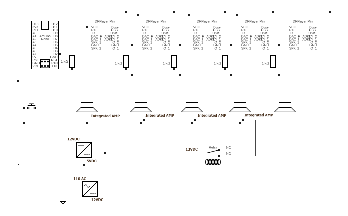
I have built a basic dfplayer circuit with multiple players all coming off of the same input. There are five dfplayers that all take their cue from a single arduino pin.
Here are some notes on this drawing:
It is my first, so I might have made a mistake especially where ground is concerned. I have positive and negative going into the power supplly as well as the 12v-5v module (https://www.allelectronics.com/item/usb-5v/usb-charger-module-dc-dc-conv./1.html).
Let me explain the purpose of this circuit -
It is a doorbell that I had help from this great community to build (Best way to play multiple audio files (each on its own speaker) simultaneously). It worked great, after a bunch of tries and a lot of learning (the most useful realization was to plug the dfplayers into headers so i can swap them out easier). When the doorbell button is pressed the arduino starts five different dfplayers going simultaneously. Four of which go to powered speakers located on different floors of a house. Each speaker plays its own track, which are parts of the same composition. When the BUSY pin of the dfplayers registers low the relay opens the 12v circuit which powers the amps which are part of every speaker (AX510 computer speaker, wall mounted). The purpose of the relay is so that when the doorbell is not playing you don't hear amp noise. The last, un-amplified, speaker has the entire piece of music and in played on the front door speaker.
It was probably the fifth incarnation of this that finally worked, wired as shown, EXCEPT, that it only had four speakers, not five. Once installed we realized that we needed one more channel, so I added one more. The dfplayers are getting their power from the 5v power module, not the arduino (I didn't want to overload it). I have also, since only connected to one busy pin, since they are all playing tracks of the same length I didn't think it would matter, plus, I didn't know if hooking the BUSY pins of the arduinos together would possibly cause an issue.
So, that is what I have built. Many of the dfplayers literally smoked, so I not sure what happened there. A few of them have never worked, right out of the package. They onboard LED is barely lit when you give them power. They produce no sound when plugged into a socket where another dfplayer works just fine.
and here is my diagram:
And here is my code:
#include "Arduino.h"
#include "SoftwareSerial.h"
#include "DFRobotDFPlayerMini.h"

//Start  serial port
SoftwareSerial mySeria1(3, 4);  // RX, TX - I didn't end up using port 3

// We declare variables for the  dfplayer
DFRobotDFPlayerMini DFPlayer1;

void setup() {
  // definition of the button connected to pin 2 and GND
  pinMode (2, INPUT_PULLUP);

  //We initialize the serial channel
  mySeria1.begin(9600);

  // initialize the player
  DFPlayer1.begin(mySeria1);

  //Default volume at 20
  DFPlayer1.volume(20);  //Set volume value (0~30).
}

void loop() {
  if (digitalRead (20) == LOW) {
    DFPlayer1.play(1);

  }
  delay (250);
  while (digitalRead (2) == HIGH);
}
One more thing - the BUSY pin give 3VDC high and 0VDC low. It worked when I hooked it up to a JK1 relay module (https://www.amazon.com/gp/product/B07874KSLY/ref=ppx_yo_dt_b_asin_title_o03_s00?ie=UTF8&psc=1) which has also recently stopped working. So perhaps I have something afoot.
I am not sure but you have the busy pin on each player linked together and with the return from the relay. I believe the busy pin is to signal that the device is playing hence an output. Connecting them all together I think is a mistake. Also the relay should not be part of it at all. Hence one busy to the arduino on a pin and relay on signal to another pin. Either way I would change something or you risk more failures which I am sure you do not want.
Yes i would agree with @anon50242852 that is probably what is killing your devices.
I would also add that all the grounds on the DFplayers while being linked are not connected to the ground of the Arduino like they should be, but maybe that is an error in your diagram.
In addition pin 2, is just relying on the internal pull up resistor. These are quite weak and not really suited for a long distance. The long wire here could be picking up high voltage interference. I should add to pin 2 a strong pull up resistor, say 1K from pin 2 to 5V, along with a 0.1uF ceramic capacitor from pin 2 to ground.
The relay wiring looks very odd. You have 5V going through the relay coil and then on to power the DFplayers on the other side of the relay coil. Also you have no reverse biased diode across the relay. This will cause a negative voltage to appear on the DFplayers power supply which could / would kill them.
I have already removed that aspect of the design. Only one dfplayer BUSY pin is being used right now as I realized that linking them was possibly a bad idea. The purpose of the BUSY pin was to tell the arduino when the song was over. Because there was also a voltage drop on the line I used that BUSY pin to signal the relay when to power the amps on and off as well. Do you think I should move that to a different BUSY pin?
The grounds on the dfplayers are absolutely connected to the ground on the arduino. That was simply an error in my drawing. Thank you for pointing that out. It means a lot to me that you are taking the time to study it enough to find that.
What do you consider long distance? There is probably 6-8 inches of wire max between the arduino and the last dfplayer. Please walk me through this part as this is beyond my easy comprehension as to what this does -"I should add to pin 2 a strong pull up resistor, say 1K from pin 2 to 5V, along with a 0.1uF ceramic capacitor from pin 2 to ground."
The relay wiring is different in reality than in this drawing, I was limited to the relays they had on hand in the application. I am using a relay module that has three pins- +,- and signal. I am powering the relay module with + and - and then connecting the signal pin to the BUSY pin on the dfplayer. When the dfplayer starts playing the current on the BUSY pin drops from high to low. This tells the relay to switch, which has worked perfectly for weeks. In my previous comment I mentioned the possibility of moving the signal pin to the BUSY pin on a different dfplayer. Do you think this would change anything. Every dfplayer is playing a track of identical lengths, so that is not an issue.
btw, using the BUSY pin to switch the relay was suggested to me in the other thread by another user. ...for what that is worth.
The internal pull up resistors in the Arduino do not pull up very strongly. An input pin if left to its own devices will "float", that means it will act like an antenna and pick up all sorts of electromagnetic signals, like mains wiring radiation, radio stations, interference from nearby motors in refrigerators, florescent lights, passing motorcycles, nearby taxis, mobile phones and so on.
A floating input can read as LOW or HIGH at random. The good news is that these interference signals are quite weak and so if they are given a bias signal in the form of a connection to 5V they will not be affected by interference. Unfortunately you can't connect the directly to 5V because that would cause a short circuit when you press a button connecting them to ground. So what you actually do is to connect a resistor between the input an 5V to overcome this interference. The lower the resistance the "harder" they are pulled up and the more interference they can put up with before succumbing to the interfering signal. The built in pullup resistors, while being a lot better than nothing are not very strong which is why I suggested putting an extra 1K pull up resistor in your circuit.
I am not talking about the DFplayers, but the wire that goes down to the front door bell push button. A long distance would anything over six feet or so.
The capacitor also helps suppressing interference by supplying, in effect, a low resistance path to ground for AC signals. That is what capacitors do.
We can only know what you tell us, and we can only comment on what we are told and see. This is why it is vital that schematics are accurate.
I think you should connect all the busy pins to different Arduino inputs, and then use software to look at them all and then decide what to do.
You should not be driving a relay coil with that output.
I only did because someone on here suggested it. I can drive the relay with the arduino but every time I tried I couldn’t get the code to work.
Regardless of whether you drive it from the DF Player or the arduino, you still can't connect a relay directly to the pin. You will need a relay driver.
I am using a relay module, if that changes anything. I linked to it in the explanation.
Who?
"Integrated Amp"?
You schematic shows that you have the speaker output going to an external amplifier? You had likely better use the other outputs for that (DAC_R, DAC_L, pins 4, 5).
In a previous post about this circuit, which I linked to earlier, someone suggested I use the busy pin to open the relay.
I am using a Del sound bar, which I linked to. It has an onboard amplifier which has a 12 volt DC input. I am running the power through the relay so that you don’t hear speaker noise when the doorbell is not playing.
The speaker out is not GND referenced, but the "DAC" outputs are.
I am running a mono signal and every Dfplayer setup I have seen has speaker hooked to speaker leads, not DAC. please explain why DAC is better, I don’t understand. And please note, In the drawing I inadvertently left out that the ground loop of the dfplayers IS grounded to the arduino.
The speaker output is differential.