This was more difficult than i first thought. I got the engine running with som simple code adjusting pwm out, that controls injector flow. It is extremelely responsive, say running at idle requires adjusting pwm by 3-4 units. My problem is that i want some sort of pid control that adapts to different running conditions, keeping idle at a stable 1000rpm. Now it idles on a simple formula like rpmset / rpm * k = pwmout, it works fine but turn on the lights and engine revs falls like 100rpms. There are so many factors to compensate for: enginge temp, air temp, fueltemp, load on generator, ac, power stering, clutch engagement.
So how can i get a pid regulator regulating between so small changes in output, but still reacting fast enough, It is not necessary to change more than 1 unit of pwm to get stable idle if nothing changes engine load, say keeping nice idle is done at one point by adjusting between 95 - 96. at 95 revs slowly drop and at 96 revs slowly rise.
I tried bretts pid library and used many different settings and sampletime but no luck. I can hear it trying to work changing. Narrowed down outputlimits to say 94 - 97. All the time it changed output all way out to limits giving engine a very rough idle. It basically controlled idle by changing output between outputlimits. Want it to regulate very very small. Or could i make pid assist my formula that already sort of works?
very cool project. pid loops are very difficult to work with. my first suggestion is to not use a pid loop and simply check if the rpm is where you want it and adjust the throttle up or down. you definitely need to make your adjustment finer.
One problem that you have to consider is the response time of the engine to input changes as compared to the time it takes for the Arduino to come up with a new value. If your program is expecting the emgine to change in 1/4 second and the response time is more like 2 seconds then the control value is going to be fluctuating al lot and possible even hitting limits.
A PID loop takes 3 variables -
The proportional - We want 1200RPM, Idle is 1000, max is 3000, difference between idle and max is 2000, so we want an initial value of 10%. Integral is compensation for last error, and adds some percentage of the last error - Okay - we are running at idle, 1000 RPM and the lights are turned on. RPM drops to 970. so our last error was 30 RPM so we add 10% so our output value changes +3. the Derivative value is an accumulated error - perhaps the last 10 erro values added together and a percentage of that added to the output.
So - how fast does the PID update, How fast does the controlled device respond, then get proportional working fairly well under "normal" conditions, then add in the I term, then work on the D term.
Not that advanced projekt this, dont know what you want a diagram of?
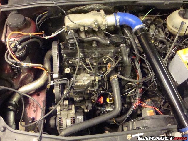
It all runs on the car battery / alternator. Driving a mosfet think it was ifz44. Logiklevel so basically driving i straight from the atmega. Just a diode to catch flyback 1n4007 i think. Controls pumps internal regulator. Pwming this mosfet for throttle.
pwmout = rpm/rpmset*k + tps
A gt101dc counts teeth on kampulley, signal to interrupt - calc rpm.
Potentiometer for throttle.
Never actually got the time to get this "finished" but car still is daily driver... Adjustment for fuel density and engine temp by potentiometer, or hand throttle...