Differential Pressure Sensor with 4-20mA Output

I am not an electrical engineer, and I don't know much about electronics. I'm an IT guy and typically write programs in C# and manage SQL databases and such, but I have been tasked with a project that requires me to assemble some electronic components.

The Facilities Maintenance Director of our company has asked me to start logging differential pressure readings from the 12 filter houses throughout the plant into a database. There are analog needle-type gauges on each of the filter houses, and machine operators are supposed to occasionally look at these gauges, and then react if the differential pressure is either too high or too low. The operators NEVER look at the gauges, and it's a problem when filters get clogged or a hole gets ripped in them.

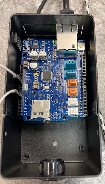
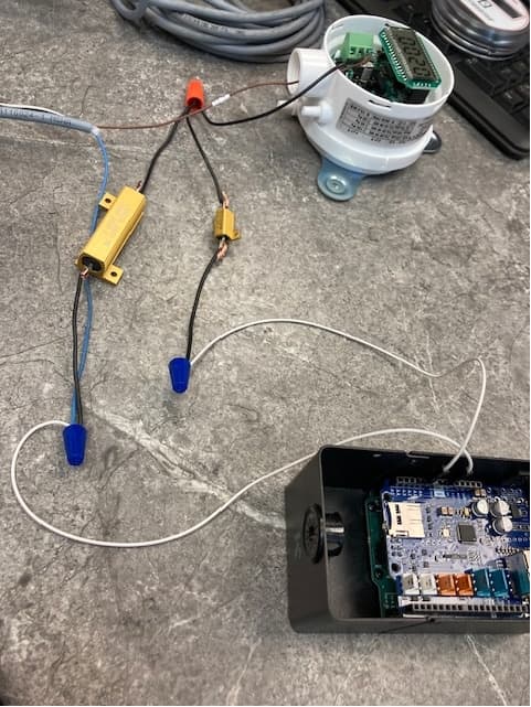
I have an Arduino Uno Rev3 with an Ethernet Shield. I also have a Dwyer MS-621-LCD, which outputs a 4-20mA signal of its differential pressure reading.

I have been reading numerous posts on this forum about how to connect the differential pressure sensor to the analog input on the Arduino Uno Rev3.

There is a 24V power supply for the Dwyer differential pressure sensor, and the Uno is powered separately with POE from its Ethernet connection.

I have gathered that I need a 250 Ohm resistor that will convert the 4-20mA signal into a 1-5V signal.

There also needs to be a 10,000 Ohm resistor that will protect the analog input on the Uno from being fried.

Here is my rudimentary wiring diagram.

My question is regarding the different specifications for the resistors.

For the 250 Ohm resistor and the 10,000 Ohm resistor, do I go with an 1/8W, 1/4W, 1/2W resistor?

How important is the tolerance? I've seen 0.1% or 5% tolerance on resistors. I'd like the readings to be as accurate as possible, but I don't want to spend more on 0.1% tolerance if it's not actually going to have that tolerance. Are the advertised tolerances telling the truth? I suppose there is no way to tell other than to just know what the trusted name brands are.

I'm hoping that these will be a couple of easy questions for the seasoned experts on this forum, and then I will be able to order a couple of the correct resistors with confidence to assemble a prototype to start gathering differential pressure readings.

Thanks.

It's quite unimportant in your simple circuit. The 10k resistor can be 5k or 20k as well, it only protects the analog input. A deviation of the 250 Ohm resistor can and should be compensated in code, by a caiibration factor. With the default Vcc reference (5V) the measured value also depends on Vcc. If precision really is important you can use one of the more stable built-in reference voltages or more precise external ADC modules. In your case I think that 10% were acceptable for failure detection - ask your Maintenance Director!

Power is low, neglectable on the 10k resistor. Calculate the power of the other resistor yourself, from

P=I²R = 20mA*20mA*250 = 400µ*250 = 100mW.

Those tolerances are supposed to represent the maximum spread of values, in percentage difference about the nominal value, measured with certified instruments, from a collection of samples. You must read the manufacturer's data sheet to see what is actually stated.

The manufacturer's data sheet is a legal document and they can be held accountable for the contents.

As stated above, you will probably need to calibrate your final setup, using measurements taken with professional instruments as the standard.

This won't help with values taken

Depending on local law an eventual compensation will not exceed the price (replacement) of the offending parts. For reliable products an input quality check is indispensable.

Obviously.

The "legal document" term indicates only that the manufacturer's claims are to be taken seriously, unlike for outlets like Alibaba, Amazon, eBay and the like, where outright fakes are common.

1 Like

Do you know how to solder?

Unfortunately, no. I don't think that I have soldered anything since my junior high Electricity class way back in the mid 1980's.

Well how were you planning on connecting everything?

Provided nothing ever goes wrong.

Thank you for replying to my post.

For my initial swing at making a prototype. I bought a HS50250RF-ND and a 2485-HS1010KJ-ND from DigiKey.

This is what my prototype setup looks like...

Prototype

I created a simple program from samples on the Arduino site, and I have this little webpage that shows what's on the analog inputs.

web

Perhaps I'm barking up the wrong tree thinking the resistors are the problem?

The LCD on the differential pressure gauge is bouncing around 0.0020 to 0.0024.

The number on the webpage is bouncing all over the place with seemingly random numbers from 0 to 400 or so.

It seems like there is no correlation between what the LCD reading is and what is showing up on the web page.

I know that I need to somehow convert the number from the webpage to whatever it's supposed to represent in "inches in water column", but it is swinging pretty wildly and the LCD is fairly steady. That's why I was thinking the resistor tolerances might be a factor.

The 250 Ohm resistor is +/- 1%, so I thought that would be ok for this project.

It doesn't need to be super precise or anything...

If the differential pressure is trending up, likely the filters are getting full and need to be changed.

If the differential pressure is low there's a tear forming in a filter. If it's 0, there is a big hole in a filter or a filter has fallen out completely.

My 10K Ohm resistor can handle up to 10W and my 250 Ohm resistor can handle up to 50W. I realize now that both resistors are way overkill because I really only need to handle a tiny fraction of 1W.

Kindly excuse my electronics ignorance. I'm trying my best to figure this out.

Are my electronic components the problem?

Does the problem lie within my program, and I need to convert the numbers to "inches in water column" to be closer to what the LCD reading is?

Is there electromagnetic interference bouncing around my office that's affecting the A0 input? Is that why the webpage readings swing so wildly?

I figure I will have to buy some breadboard and a soldering iron, and use tiny resistors such as this?

I'm hoping to fit a small board containing the resistors into this small space inside the Arduino enclosure.

Interesting... I turned OFF the power supply for the differential pressure sensor, and there are still readings for all the analog inputs that fluctuate to random numbers.

readings

Perhaps I have nothing going to A0 at all?

You have that wired wrong.
I hope you did not damage the Uno.
Follow your schematic in post#1

Whoa! You're right! Thanks jim-p!

I switched the A0 and the GND, so now it should be wired correctly.

Now A0 says reads 1023, and stays there all the time.

1023

How can I tell if A0 is fried?

Can I plug it into A1, A2, or A3? Or do they all get fried when it's wired wrong?

  • Put 2.5v on A0, write a small sketch to read A0, you should read ~512.

Datasheet says the sensor can operate with voltage as low as 10V. If you're using 24V the 10K resistor in series with analog in should be at least 24k to prevent current greater than 1mA from flowing through the input pin's ESD protection diode in case of circuit fault. If power supply were 12V, that resistor could be lowered to 12 or 15k

https://dwyer-inst.com/PDF_files/2021/INTL/MS.i.pdf

Ok... yikes! Thank you for replying to my post! I have shut everything off and unplugged everything. I will have to get a 24K resistor to put in there instead. Hopefully my A0 isn't fried, since I apparently have been sending too much to it this entire time.

You're OK as long as the circuit from A0 to GND through the 250Ω load resistor is good, but if there is a loose connection or "iffy" solder joint the full 24V could be applied to A0. The 24k resistor would limit current flowing into the pin, then through the ESD diode into the 5V bus to 1mA max.

This is correct, sort of. The sensor requires 10 volts minimum. If you use a 12 volt supply the 250 ohm resistor will drop 5 volts leaving only 7 volts for the sensor. 24 volts is the usual supply voltage for 4-20 mA loops. Most instruments (sensors/transmitters) can tolerate about 40 volts. It is not common today but in the pre computer control age several devices may have needed to use the same signal, each with its own 250 0hm resistor.

When I first started in the field 10-50 mA loops were still being used with 80 volt supplies. If you weren’t careful you could get a bit more than a tingle when working on them.