One thing I have noticed is that the 621 model you have chosen has an input range of 0 - 0.5 inwc. The Magnahelic gauge you show has a range of 0 - 80 mmwc. 80 mm is ~3.1 inwc. If that is the expected range of measurement you need a different model.
250 Ohm resistor: Digikey has 0.1% .4 watt for $1.25 no reason not to have the.
Power supply: You have to be careful about connecting the negative of the 24V sensor supply to the negative of the POE supply. Ideally you would want the Arduino powered from the 24V supply and the ethernet connection isolated. You would need a converter to reduce the 24 V supply to 8 or 10V to power the Arduino. Consider one of these commercial supplies DO NOT purchase a cheap supply from eBay or China.
12 Inputs: Arduino had 6 Analog inputs. You could multiples them with most any analog multiplexer. Or better yet a 12 channel A/D device like the MAX11604. The thing about the MAX unit is you can purchase an evaluation kit to use so you don't have to muck with surface mount devices. THen for isolation you can use one of these already prebuilt.
With what I know so far, you are better staying with the 4 to 20ma devices. I'll guess the sensors are spread out over some distance in a likely electrically noisy environment.
In my experience it is foolish to "cheap out" for a one time device. And any failures will make you look bad.
I did some research and found that I was remembering incorrectly. The forward voltage does rise quite rapidly with increasing current but it does not rise and then drop.
It occurs to me that we haven’t discussed how you intend to implement the installation. Are you going to bring all the 4-20 signals to a single place or have one Uno for each sensor and run Ethernet for each one?
The first option is how it is normally done. The second option would make using a voltage output from the sensor more doable with a short wiring distance between the sensor and the Uno.
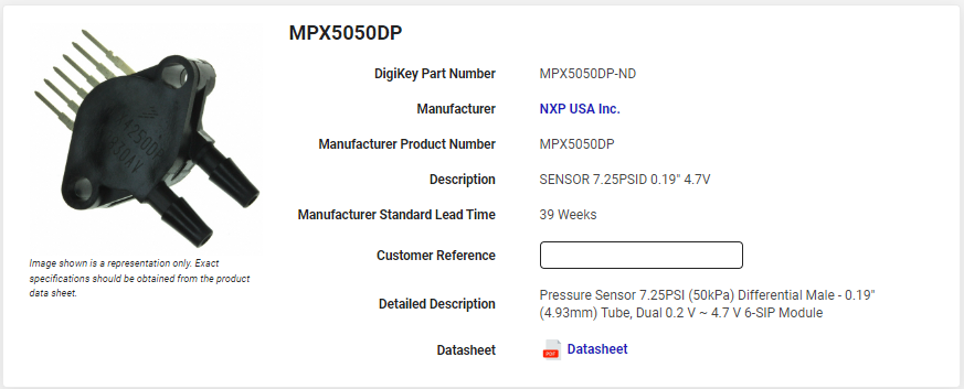
I don't know why I thought I needed to have that expensive external differential pressure sensor and complicate it with resistors and whatnot. This MPX5050DP seems to be a much cleaner, more simple solution.
The specs say it draws 4.75V ~ 5.25V, so hopefully the 5V on the Arduino can handle that.
The specs also say it outputs a 0.2V ~ 4.7V signal, and please forgive my ignorance, but I assume that I can apply whatever unit of measure to that I want? I could have "inches of water column", or "mm of water column", or PSI, right? I'd just have to somehow calibrate the sensor so 0.2V is 0 and 4.7V is whatever the maximum value turns out to be.
I tried to ask my Facility Director guy about what the max differential pressure would be inside the filter houses. He told me that he didn't know, and that I'd have to go around to all the analog gauges and see what the unit of measure is on the gauges and record what the number ranges are. Sheesh, ok, thanks a lot for the assistance in figuring that out.
The MXP5050DP says its max pressure is 29.01PSI (200kPa), and I don't think the filter houses would ever have a differential pressure that high, so it might be a bit overkill that way.
That is the max allowable D/P. The working D/P is 0 - 50kPa which is 0 - 5098 mmwc. 80 mmwc is only ~ 1.5% of that range. That is only 16 different values on a 10 bit A/D converter, unless you use some external electronic scaling with an op-amp circuit.
Better to use the ready made solution that best fits your needed pressure range.
After lunch today I'm going to go around the plant with a clipboard and write down the units of measure and what the min/max numbers are on each of the 12 gauges. That should give me a good idea of what differential pressure ranges are needed.
Thanks to everyone for their assistance and lending their expertise on this project!
I went around and recorded the info about all the gauges. Most of them are "mm of water" and are 0-80. There's a few that are "inches of water" with 0-3, which converts to 0-80 "mm of water" I believe.
I took a photo of this one gauge, because it's right at the mark where the filters are likely full and need to be changed.
By the Sharpie marks on the glass of the gauge, it looks like if the differential pressure falls below 18, there's likely a tear in the filter or the filter is falling or has fallen out. If the differential pressure is at 62 or more, the filter is plugged and needs to be changed.
I say this because I've spent some years evaluating pressure transducers for automotive applications. The issue is the zero drift, aka the output value when no pressure is applied. The zero drift on the MXP5050DP has a range the covers most of your measurement range.
I would say that $200 for a differential pressure sensor is probably my top end.
I have like $65 in Uno R3, Ethernet shield, and POE splitter, so add $200 for a sensor adds up to $265 for each data logger. If I need 12 of them, $265 x 12 = $3,180, I think my boss wouldn't have a problem approving that.