I'm trying to interface with a device that should apparently output a 150V PWM. It's actually an industrial halogen light dimmer, but I want to use this PWM signal as a control PWM. My plan was to drop the voltage to 5V using a simple potential divider (I'm not pulling any significant current - signal only) to be left with a usable 0-5V PWM.
Problem is, I built a potential divider, tested it on the 150V 'PWM' and got some strange results.
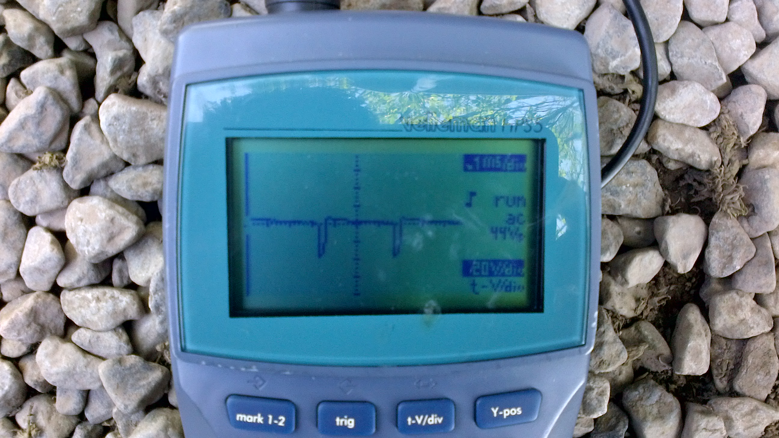
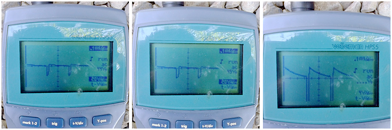
My PD is made up of a 10k and a 330R (high wattage in consideration of the 30x volt drop). I expected to see a peak voltage of around 4.5V after the PD, but instead the peak was reaching nearly 50V and the pulse shape was not square. It looked more like the signature of an inductor - See attached pics
I double and triple checked my PD and it's correct. Is there something I'm missing here? What do you think could be causing the high voltage to be passing straight through my PD? And why the odd shaped wave rather than a pure square wave? Could it be that the device actually doesn't output true PWM or is it more likely to be something I've missed?
Just a side note, when I put my multimeter across the 150V terminals and set the duty cycle to 100%, I do get 150V DC.
Your 330 ohm resistor is wirewound - you definitely don't want wirewound since
they are inductive.
Your divider should use much higher value resistors, something more like 5k or 10k in
the low-side is appropriate. Perhaps 150k and 4k7.
Since 150V DC is unremittingly lethal you need to take special care constructing
such a divider:
Use 2 or more resistors in series for the high-side, so that a single component
failure cannot destroy the low-voltage circuitry or cause electrocution. Similarly
using two resistors in parallel for the low-side would reduce the risk of single-component
failure from generating large voltages.
Use large resistors rated for high voltage - these are long enough that an ant
crawling over the board cannot short it out, and reduce the risk of flash-over in
humid conditions.
insulate the back of the board so that stray fingers cannot touch the high voltage
side.
Note that your existing divider takes 15mA which is enough to stop your heart - if
the low-side resistor or ground connection came adrift it too could be lethal.
A much better way to interface would have been an opto isolator, all things considered,
high voltage DC is more dangerous than AC...
I hadn't considered that wire-wounds were inductive, however, my resistors are metal film 2W (paired up for 4W at correct overall resistance). Would metal film resistors have a similar effect? Perhaps the low values alone are giving me the bad output?
I wanted to drop the voltage to 5V for my opto isolator which stands between the signal and the micro. Do you know of an opto isolator that would take a 150V PWM input?
MarkT:
If the resistor isn't wirewound then you are seeing the genuine waveform.
Why do you say its PWM by the way - I took that on trust, but perhaps its
a flyback converter output or somesuch?
This, too. A switch mode power supply is basically PWM charging up a capacitor. The non-square signal you're seeing might be the capacitor charging/discharging.
The PWM of that controller is usually called phase control. It is basically an industrial light dimmer. A triac is turned on after the zero crossing, wait later and the light is dimmer.
http://www.pic_examples.byethost3.com/Dimmer.html
It requires a load to work. Without sufficient load, the triac won't stay turned on and you'll just see a short pulse.
A peak reading DMM used without a load on the dimmer will likely read 150V over most of the adjustment range, or it may read values that don't seem to correlate with the setting.
Put a 100W incandescent bulb on it and try again.
Because of that waveform, though, you can't just read the peak voltage to see what the percent power is set at. You'll want to look at the time when it triggers after the zero crossing.
Hi, the dimmer, can you show us a picture of it, and or its specs, is the 150V output going to anything other than the divider?
What controls the dimmer?
Is the dimmer supplied from the mains power supply?
Firstly thank you very much polymorph for such a comprehensive response. I think you may be right about phase control, although see new info below.
Also, sorry about the mega size jpegs - they were straight from the camera on my tablet. I've attached a cropped and resized version of the original scope readings.
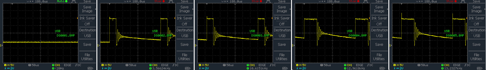
I have since managed to get a digital scope onto the output and attach the results. These readings are taken with a 15K load resistor. Kinda looks more like PWM maybe, but that said, there's something unusual with it. Note the frequency increase. Images 1 through to 5 are steadily increasing the control from 0-100%.
Does this throw any more light on the matter or make things more confusing perhaps???
TomGeorge - The dimmer is actually on a subsea vehicle. The board is inside a pressure housing so not much to look at. I've tried to get specs from the manufacturer but to no avail. The output is coming straight from the dimmer with nothing else attached. It's a spare dimmer for a halogen lighting option - the vehicle is using LEDs so the halogen dimmer is otherwise redundant.
Hi, I think you will find that the five traces show that you have fixed frequency and adjustable duty cycle.
The trace display is 6.8 x 50uS= 340uS, approx 2941Hz, in all of the screens, the digital display is being fooled by the ringing on the trace.
What are the inputs and outputs to the dimmer, and what has it got written on it.
How also a diagram as to how you are measuring the traces, is the input from a potentiometer or from another control circuit.
Please some sort of diagram/picture of the device and how you are connecting it.
I'm not sure where the 150V is because the trce shows 15V pulses unless you are using a 10x probe???????????
I second what TomGeorge said, now that I can see the images.
So this is -not- running from line voltage, but is straight PWM from a DC voltage.
What I said about a load still applies. You can't simply apply a DMM to a PWM and get a meaningful reading, unless perhaps you have a true RMS reading meter and the PWM signal is within the meter's frequency range.