It's got I/O pins, and they have pull up resistors, though it seems they have a smaller value than on a full arduino.
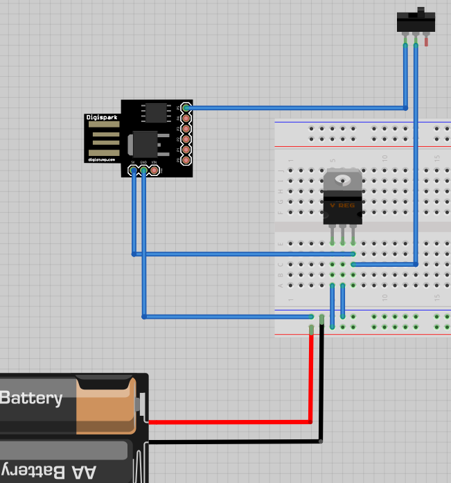
I'd like to sense a switch closure with the Digispark, and I'm not sure if I need another resistor or not. My EE skills are still pretty low. I used Fritzing to diagram what I was thinking I could do. Will this work? Or will it break something? So far this weekend I've already fried a few LEDs, so I'd rather ask before I burn out a digispark.
The reason I'm asking is this blurb:
Digital Read:
NOTE: The internal pull-up resistor (turned on by calling digitalWrite(0) after setting the pin to output, where 0 is the pin number) are much weaker (about 25 kohm) on an ATtiny than on an Arduino, so the onboard LED interferes with them. If you need them, you can use a different port. Change your circuit to not need the internal pull-up, or cut the LED trace. For Model A this would apply to P1 for Model B this would apply to P0.(Model Identification)
You'll be fine using the internal pullup, unless it's in a very noisy environment and/or the physical switch is very far away from the microcontroller.
Turns out I won't be using a switch; the switch will power the unit on or off. However, I will be using a circuit detection the same way, and that circuit will have many feet of wire. Maybe 20 - 60 round trip, with power being sent by a 7805 regulator through all that wire, then into the input.
Sorry to change things up, working on the fly here.
edit 2311 09-22-2013
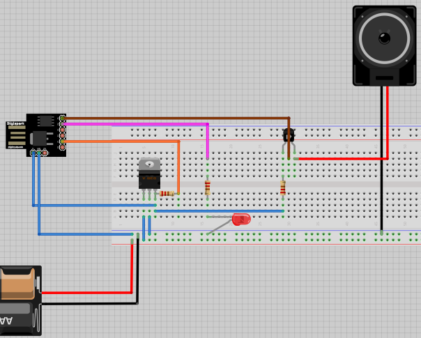
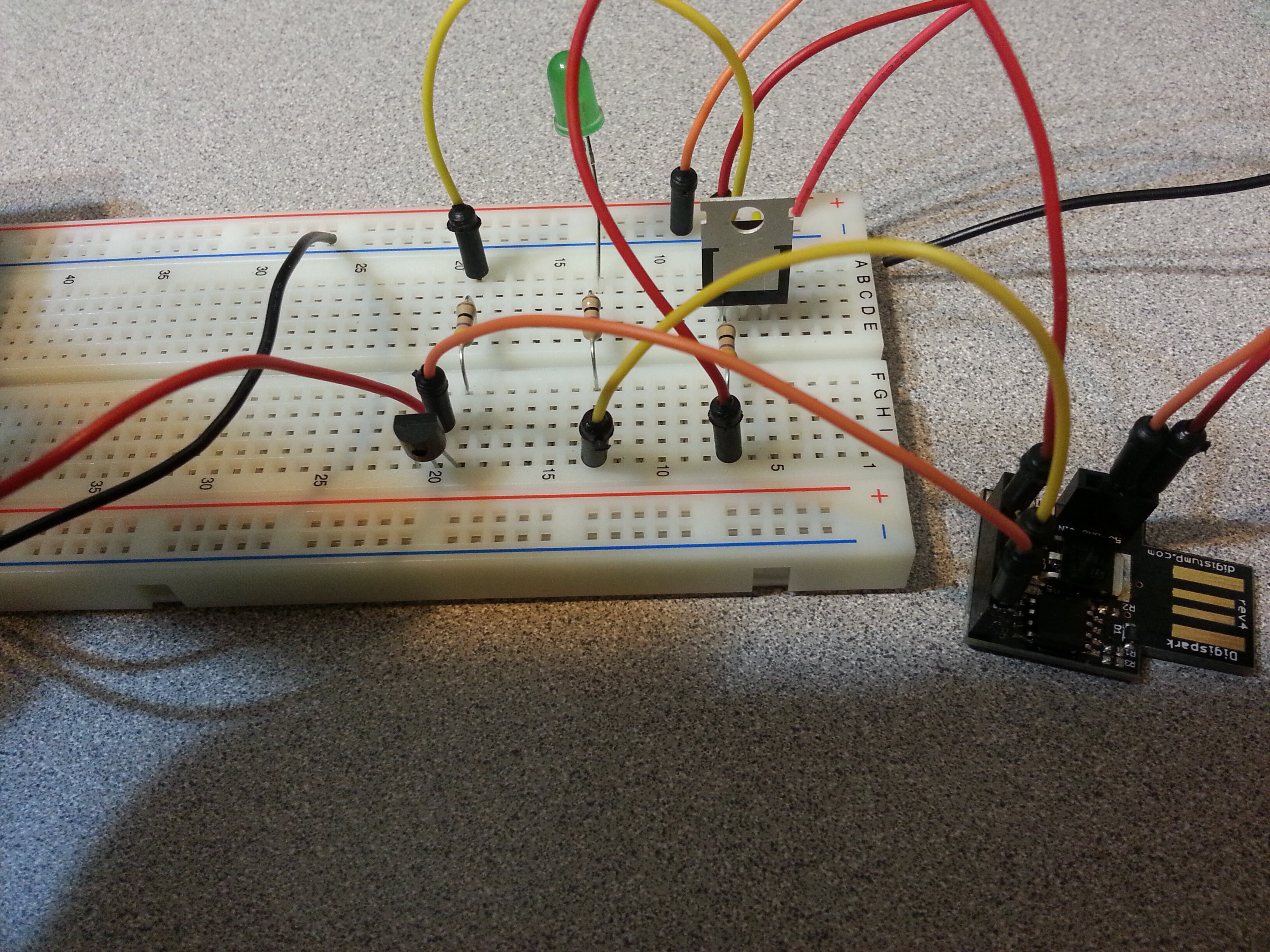
I've drawn something very similar to what I have bread boarded out. The paths work out the same, I just spaced it out so the drawing is readable with the particular view of the software.
The orange line is a manual test right now. Eventually that will be a set of RCA cables that loop around something. This is the wire that will be 20 - 60' round trip that I referred to.
In testing, i noticed that pins 5 and 6 yeilded different results when they were set to go high. Pin 5 was able to drive the LED and the transistor/siren fine. Pin 6 is not able to drive the LED to the same brightness, nor is it able to drive the transistor/siren (no sound). I don't understand why this is the way it is.
Code I've loaded:
void setup(){
  pinMode(1,INPUT); //detects circuit
  pinMode(2,INPUT); // debug reset
  pinMode(4,OUTPUT); // LED for alarm
  pinMode(5,OUTPUT); // siren

  digitalWrite(4,LOW);
  digitalWrite(5,LOW);


} // end setup()


void loop(){

  if(digitalRead(1)==LOW){
    digitalWrite(4,HIGH);
    digitalWrite(5,HIGH);
  } // end if

  if(digitalRead(1)==HIGH){
    digitalWrite(4,LOW);
    digitalWrite(5,LOW);
  } // end if

} // end loop()
7805 will not work well trying to get 5v from a 3v (2 cell) source.
the switch will not do much trying to pull up a signal that is already up.
led is wired backwards.
resistor on the transistor emitter serves little purpose other than preventing the alarm from working.
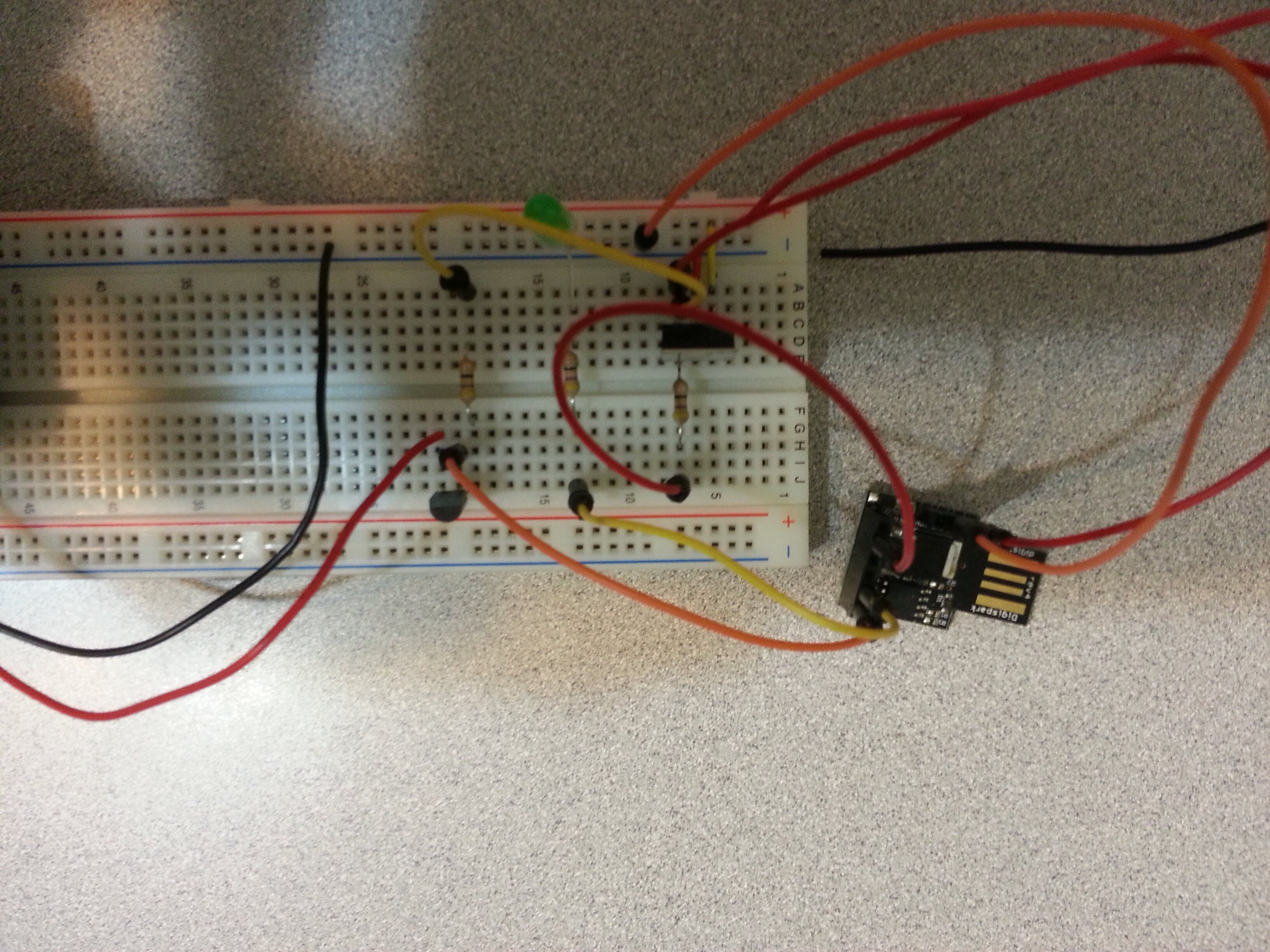
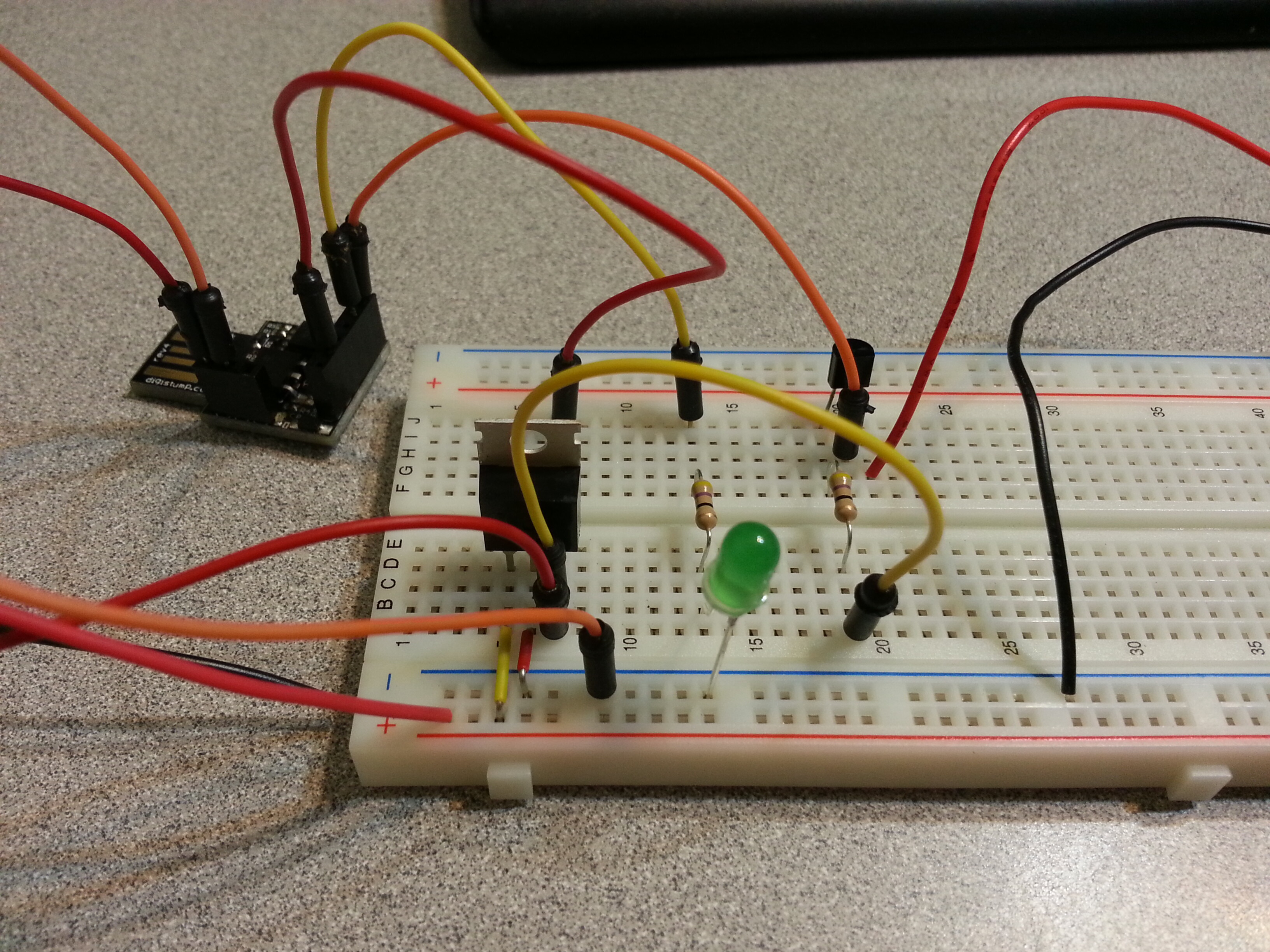
im thinking maybe youtube is not such a "great vid explaining pull up and down resistors" after all. and that diagram may not be as useful as a photo of the actual circuit.
NOTE: The internal pull-up resistor (turned on by calling digitalWrite(0) after setting the pin to output, where 0 is the pin number) are much weaker (about 25 kohm) on an ATtiny than on an Arduino, so the onboard LED interferes with them.
If you need them, you can use a different port. Change your circuit to not need the internal
Fact is, the onboard LED on any Arduino will interfere with reading using the pullup, irrespective of how strong the pullup is.
Also noted on your diagram above, is that your switch is referenced to Vcc, which is in the same direction as the internal pull-up so with nothing to pull it down, it will not be usable.
In general, it is much preferable to have all switches going to ground, for one because the internal pull-ups are available but also minimising the risk of accidental shorts to ground.
Thanks for the diagnosis. Im new to the diagram software, so you found mostly errors in my drawing. Power pack is 4x AA putting out about 6V. The LED is wired up right just not drawn right. More importantly what that means is that LEDs all adhere to a standard formfactor. I didnt know that and thats good info.
Ill try to post pics bow (im mobile) if not ill post them tomorrow.
My EE-foo is still weak so im not comfortable with Vcc. Is that positive or negative?
Why do you mention the internal LED? I left pin 0 alone so I wouldnt have to worry about it. Did I get the wrong pin?
I look at some circuits and see resistors sprinkled around like it was a sprinkle covered donut. I cant tell a rhyme or reason and putting a few resistors "to protect the transistor" is what I wound up with.
Do either of you have recommendations for free reputable sources for infoto get into electronics? The first few youtube vids had errors I could find.
allanonmage:
Do either of you have recommendations for free reputable sources for infoto get into electronics? The first few youtube vids had errors I could find.
i suggest google instead of youtube which is estimated to contain 2/3 false info. either incompetence or simply malicious intent. i hate youtube. orders of magnitude less efficient and misleading compared to html or pdf. google is your friend. "electronics tutorial" might be a good start.
depending on alarm current and noise an external regulator might be needed so thats not a problem. but 7805 is not capable of regulating a 6v source. you might investigate "ldo" type which might work. or no regulator at all with npn (im guessing the one in your circuit is pnp?) controlling it wired directly to the battery. this might be a good idea anyway since all the beepers i use generate so much noise they reset the micro if on the same rail.
in any case good to see someone not afraid to jump in. hope you get this working and sure to learn a lot in the process.