Digital Hall Effect Outputs 0.8V and < 50 mA. Ideas for triggering Arduino interrupts?

I am trying to use an Arduino Mega (rugged-circuits mega actually) based system as an electronic dashboard in a project car. The Arduino will feed a Nextion HMI as well as some stock dashboard functions like an "analog" tachometer. The mega will be monitoring multiple sensors at once, so to avoid "blocking" code I am wanting to use interrupts to read the RPM of the engine.

My issue is that the Engine Speed Sensor utilizes a digital hall effect sensor which outputs a very low 0.8V and even worse something under 50 mA. The mega needs over 3V to reliably trigger. My first solution was to just buy a voltage booster on amazon (ASIN: B08NCM9ZPQ), and this works great on the bench, however it turns out this voltage booster needs more current than the Engine Speed Sensor is putting out to trigger once I actually plug it in. Testing it with a bench power supply it appears I need over 50 mA at 0.8V for the voltage booster to actually boost over 3V.

Any ideas for an easy way to boost the voltage and current readings of the hall effect, such that an arduino interrupt pin can read them? The sensor will output 17-200 Hz at the operating speeds of the engine.

I was hoping there'd be an off the shelf solution like the amazon booster I already bought, but I suppose if noone has any better ideas I can try and make my own transistor circuit. Electronics aren't my strong suit so I was hoping to avoid doing that.

Which engine speed sensor. Did you add your own?
Did you use pull up on the pin with pinMode(), or did you use a pull up resistor?
Leo..

Did you use pull up on the pin with pinMode(), or did you use a pull up resistor?

I am using a pull down resistor I added myself. I am just using pinMode INPUT. The value is 1k since on trial and error this pulled it down to under 3V in only a couple milliseconds - higher resistance values didn't pull it down quick enough.

Which engine speed sensor. Did you add your own?

I am using the speed sensor that comes stock on the engine (12 valve cummins, came out of a '94 ram 2500). I like using stock parts since they're easy to replace should anything happen, and theoretically its a very robust sensor. It's a 3 wire, digital hall effect that I'm feeding 5V and it outputs a digital pulse (twice per revolution) at 0.8V. It's spaced about .030" from the harmonic balancer which has the 2 cutouts to trigger it (stock spec is 50 thou, I chose 30 since it seemed to output a slightly higher voltage).

edit: also BTW the 5V isn't coming from the arduino, I have a little step down buck convertor ( amazon ASIN: B094ZTG5S8) to bring the 12-14V from the battery down to a constant 5V to feed sensors. I figured the arduino wouldn't output enough current from the 5V for all the sensors I wanted to add. The arduino and buck convertor have a common ground.

I can't believe I hadn't actually thought of this, but based on your response I suppose I could just buy a different hall effect sensor and stop messing with the stock one :woman_facepalming:. I would need to machine a rigid and precise little mount for it so it would be some extra work, but the easiest solution would just be to have the sensor output the right voltage to begin with. I guess I hadn't thought through what it would take to actually just use an aftermarket sensor, or maybe I just assumed they wouldn't last.

If anyone has an easy way to fix it without having to machine a mount I'm still all ears. Alternatively, if anyone has a recommendation for a robust aftermarket hall effect that will trigger off a gap (not off a magnet), and can run up to 200 Hz in a rough environment for years without failing, that would also be awesome.

You NEED PULL-UP resistors OR PIN MODE (INPUT_PULLUP) in your unseen code! :woozy_face:
or the pull-down resistor you added is loading the possible internals ,
most Hall sensors are open collector outputs

Hi,

What does the Cummins engine manual say it the output signal should be?

What are the three wires?

Have you used a scope to measure the pulse, with and without the sensor output connected to the ECU?

Your sensor is not a HallEffect, it is an inductive sensor, as you say it does not use a magnet.
The sensor may have an open collector output, so you may need a RESISTOR between the output wire and power supply, say 4K7.

Thanks.. Tom... :smiley: :+1: :coffee: :australia:

If you have a picture of the sensor, then upload it here.
There is a lot of non-Arduino knowledge (greybeards) here on this site.

Power and pull up for sensors should generally speaking come from the MCU supply itself.
Powering things not from the Arduino's 5volt supply could be asking for trouble.
Maybe you have heard of phantom- or ghost powering through an I/O pin.
Leo..

Hall effect sensors for automotive applications, (engine timing, ABS brake systems, etc.), have a built in permanent magnet mounted next to the Hall effect and sense an air gap in a moving ferromagnetic material. They are generally used instead of variable reluctance pickups because the will operate down to zero speed.

They generally have open collector outputs and need a pull-up resistor.

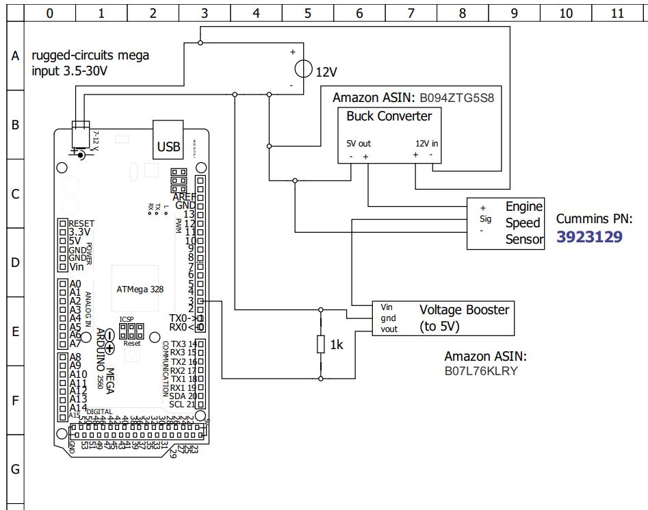
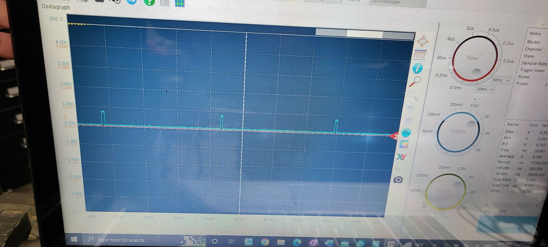
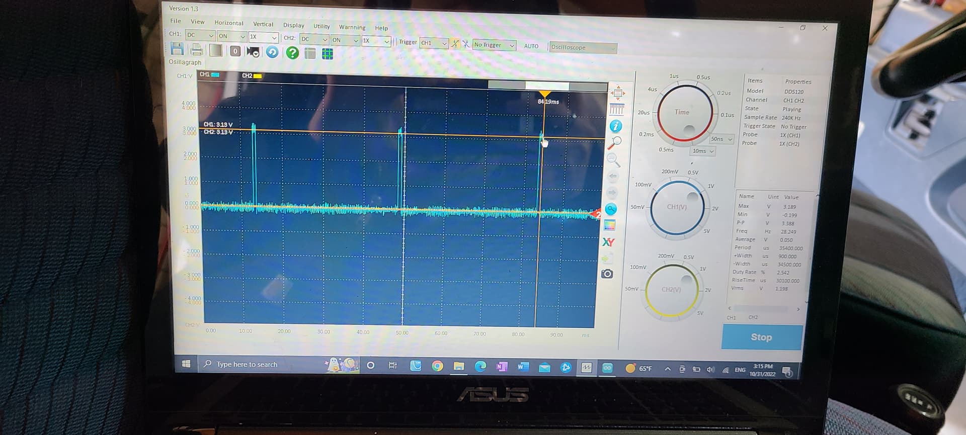
Thank you all for the input. Please keep in mind that everything about this circuit works when I test triggering it with my bench top power supply. It only stops working when I try to trigger off the speed sensor itself and the reason why is the current from the speed sensor is too low to drive the voltage booster I'm using, so the voltage never gets boosted high enough for the arduino to read it. When I'm using the benchtop supply to feed 0.8V to the voltage booster I can confirm that it triggers as expected above 50mA, and doesn't work under 50 mA. I verified with an oscilloscope that the speed sensor outputs square 0.8V pulses. I can include some code and wiring if you'd like, but it's kind of complicated and would take me a bit to draw up.

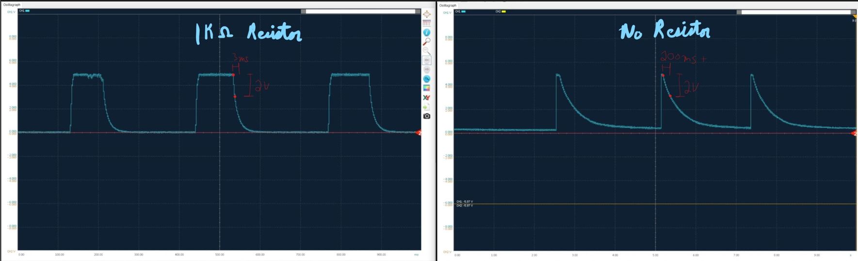
I don't understand why. The pin on the arduino is normally low, 0V WRT ground, correct? Why would adding a resistor between this pin and ground load the internals? Perhaps the terms I'm using are incorrect. I added a 1k resistor between ground, and the node that includes the arduino input pin and the 5V pulsed signal. The reason why is because in my bench testing I needed the voltage boosted signal to return to 0V quicker, otherwise it wouldn't ever fall below 3V and would effectively stay high all the time. See picture (note the time scales are different between the two graphs, first one falls from 5V to 3V in 3 ms, the second in 200ms+).

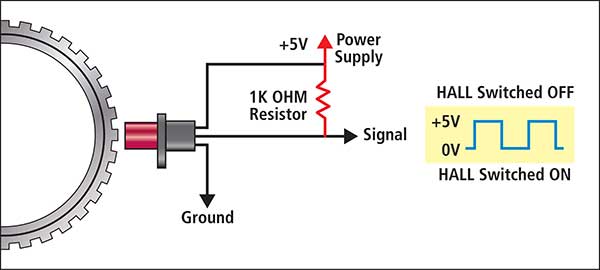
Unfortunately I haven't found an answer to this. What it IS outputting is 0.8V pulsed square wave as verified with an oscilloscope. There is no ECU (engine is mechanical and doesn't need one to run and was swapped into a different vehicle). I am feeding it 5V either with the buck convertor or with my benchtop supply depending how I'm testing it. The three wires are ground, +5V, and signal (0.8V pulsed square). You may be correct about what type of sensor it is, but I was pretty sure the manual called it a hall effect. It has a permanent magnet in it and some circuitry to make the output digital. It runs off DC. Other than that I'm not certain what it is. Perhaps it IS wired wrong but it appears to be outputting a pretty clean signal.

Sensor
See picture for a wiring diagram from the manual. It does look like the manual specifies 8V not 5V feeding the sensor, however I tested this before and there didn't appear to be a big difference (.1V or so on the output) if I feed it 8V or 5V. I will test this again to be sure, I wanted to stick to 5V since other sensors use 5V.

Hmm I haven't heard of this. is this a problem even when there is a common ground? How should I fix this, or know it's an issue? What is the recommended way to power something if it asks for more power than the arduino can supply?

This is very interesting. I tried adding a pullup resistor and there was no change. However I'm going to pull it off the car and do some testing, see if the wiring of the sensor is the issue.

Looks like I have some more testing to do, however I may be out of time this weekend. I'll try it again on 8V, and try to research the pullup resistor on the sensor some more. Thank you all again.

Do I understand you correctly that you have a voltage boost circuit connected to the output of the sensor?

What is your "voltage boost circuit" ? If it is an active circuit then it will never work.

I don't believe the 0.8V is the intended output. Automotive systems are much too electrical noisy to deal with such a low voltage.

I see in the diagram the ECU is marked to put 8V to the sensor.

So what can you test with the actual sensor? Can you simply put your oscilloscope on the output?

And "sensor return" seems to be ground.
Do you measure any voltage on "sensor return" WRT the car body.
Leo..

@buildsomething @Wawa

The OP should (if they didn't) be measuring WRT the sensor ground. An ECU "ground" is only kinda ground.

It would be good if the OP made a quick sketch of the circuit connected in the intended vehicle.

1 Like

A pictures worth a thousand words, here it is:

Actual sensor reads 0.8V pulsed square wave. See picture:

The project car is engine swapped so I can't confirm this is what the voltage always was back in the original vehicle the car came out of, this is just what it is now as wired in the schematic. It's possible you're right that it's simply wired wrong and outputting too low a signal, I'll look into this more (although the signal is very clean and consistent even if low).

Since I tied the 12V system ground into the rest of my grounds, all grounds are now common (chassis, sensor, arduino, and 5V). Only one I'm missing is earth ground :rofl:. All my measurements are WRT the common ground.

https://premierautotrade.com.au/news/diagnosing-crank-angle-sensors-CAS.php
FAST-5-CAS-PULL-DOWN

The boost converter you’ve shown is being applied completely wrong. It is designed to boost a voltage in the 1.5V - 4.2V range to 5V to use as a power source not a signal amplifier. Disconnect it and put it somewhere where it won’t be in the way. :grinning:
The Cummins sensor is listed as a 12V item by Cummins but may operate on 8V. You need to hook it up as suggested with a pull-up resistor to 8V-12V and measure the output on a scope.

Note in a vehicle ground is not ground***. GM requires the digital input of a device be able to accommodate a difference in ground (between our unit and the ECU) of +/- 2.5V. I'll guess this is extreme but gives an indication of the magnitude of what could be expected.

YOU CANNOT boost a sensor voltage using the boost converter:

  1. These converters do not react fast enough when switched ON and OFF
  2. They draw too much current.

Can you measure the sensor with the scope lead common near the sensor and with NO load on the sensor?

Are you confident your scope probe and electronics are accurately showing you the correct voltage? Do you have a X10 probe?

*** and it should be called "common" not ground.

The photo cuts off the scope probe information. Does your scope probe have a 1X/10X switch?

:white_check_mark: :heavy_check_mark: :white_check_mark: :heavy_check_mark: :white_check_mark: :heavy_check_mark: :white_check_mark: :ballot_box_with_check: :heavy_check_mark: :white_check_mark: :ballot_box_with_check: :heavy_check_mark:

This post was very helpful. After reading that article I decided to try wiring a 1k resistor from signal to GROUND since wiring one to positive didn't help. It sort of worked! For the first time I was getting 3V out of the sensor rather than 0.8V.

Unfortunately it didn't last. After only a startup or two it started spitting out 0.8V again no matter how I wired it. Unfortunately I'm really starting to think the sensor itself is the problem since everyone seems to think 0.8V output is too low, and I only ever got more than that very briefly before it pooped the bed again. I've been working on other projects but I'll pull this sensor off again and test it on the bench, and if I can't get more voltage out of it I'll either try to either replace this $200 sensor, or more likely find a different cheaper sensor (but not so cheap that I think it won't last).

See my other response above, I think I needed a pull down resistor but overall I think the sensor is just bad. Yes I'm confident the oscilloscope reading was correct, I even verified it with my fluke meter.

I purchased that convertor because the info page CLAIMED 150k Hz which is much more than I needed, and experimentally on the scope it seemed like it would switch fast enough (although not nearly as fast as they claimed). However your point two seems correct, it required too much current to run (although only barely).

It is if I wire it that way :rofl:. Although in general this is a good point, I didn't realize such a high difference was allowed. On my very custom vehicle there is no longer an ECU other than the arduino. The engine is mechanical and does not require an ECU so the arduino is only running my dashboard and eventually some other accessories (like switching on the grid heaters and such). I don't think I'll run into any issues tying the grounds together since there is no finicky engine control stuff going on, but I've obviously been wrong before :sweat_smile:.